Adjusting device used for fluid static force pump and fluid static force pump

A technology for adjusting equipment and hydrostatic force, applied in mechanical equipment, pumps, pump control, etc., can solve problems such as reducing pump efficiency

Active Publication Date: 2014-03-26
ROBERT BOSCH GMBH
View PDF12 Cites 7 Cited by
  • Summary
  • Abstract
  • Description
  • Claims
  • Application Information

AI Technical Summary

Problems solved by technology

[0006] A disadvantage of such regulating devices for hydrostatic pumps is that, for the switching position with increased po

Method used


Image

  • Adjusting device used for fluid static force pump and fluid static force pump
  • Adjusting device used for fluid static force pump and fluid static force pump
  • Adjusting device used for fluid static force pump and fluid static force pump

Examples


Embodiment Construction

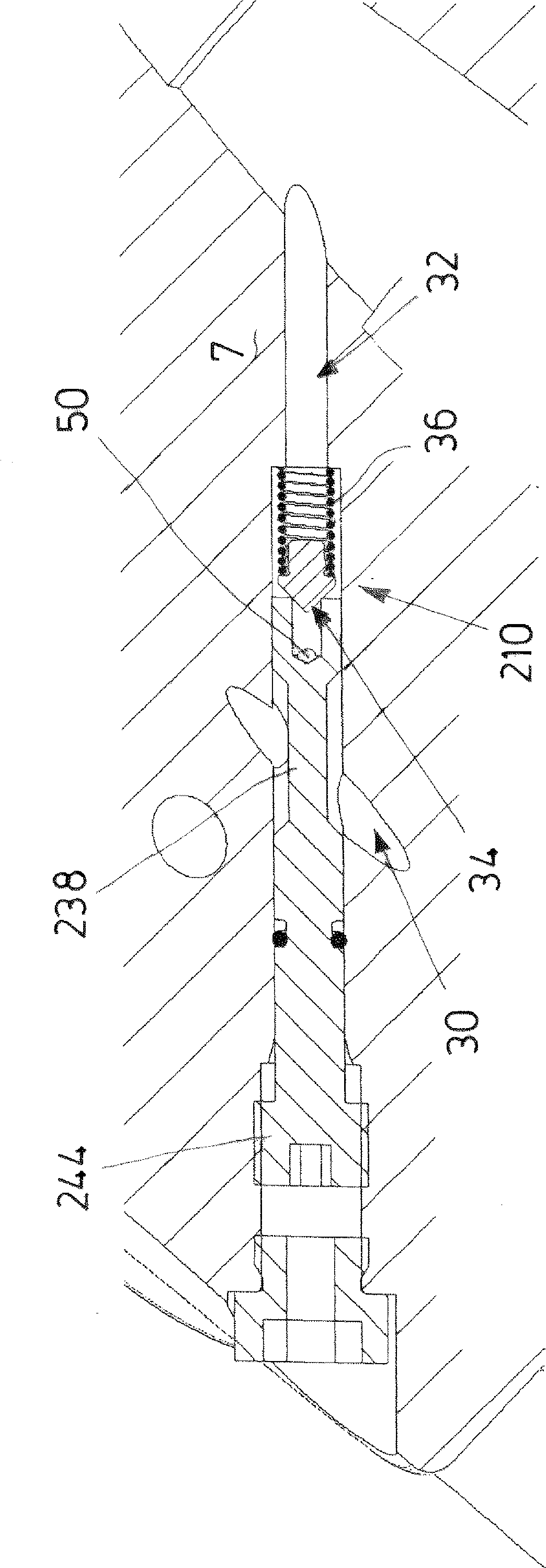
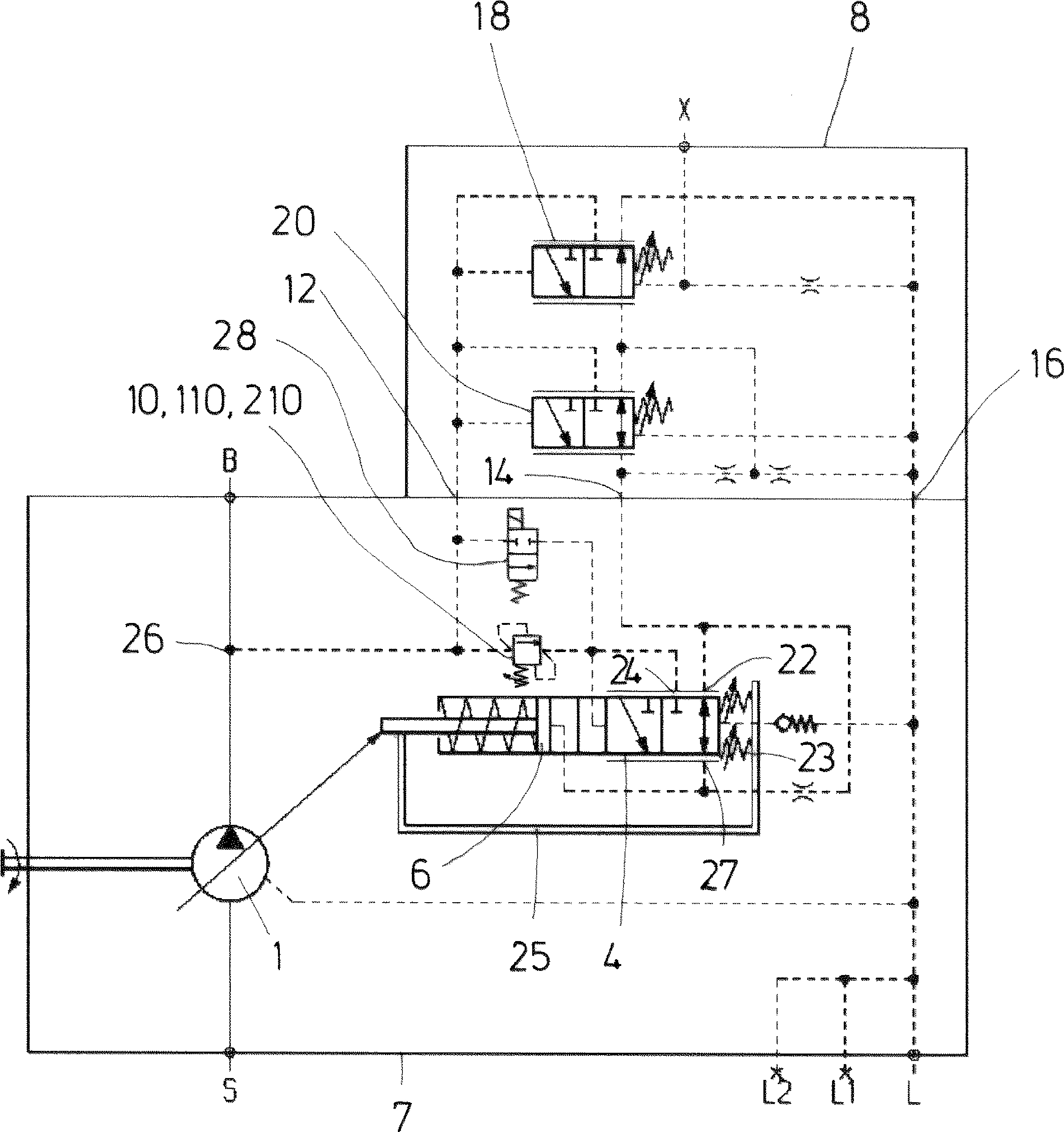
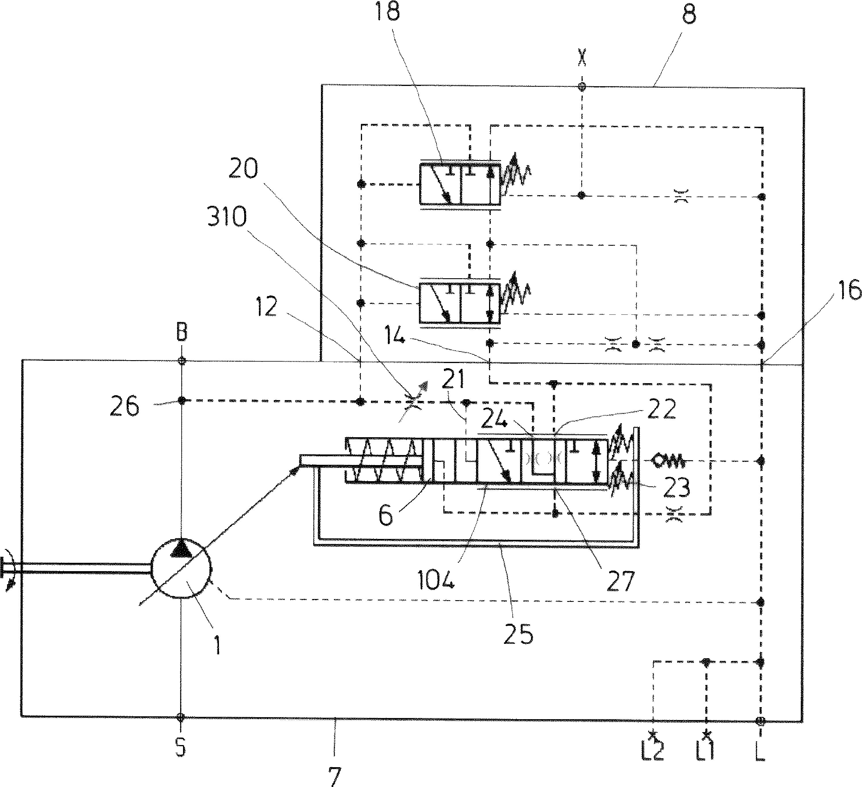
[0040] figure 1 A connection diagram of an adjustable hydrostatic pump 1 with a first exemplary embodiment of an adjusting device according to the invention for a deflectable swash plate 2 of the pump 1 is shown. Said regulating device comprises a power regulator formed by a power regulating valve 4 and a servo piston 6 connected to the swash plate 2 . Furthermore, the regulating device has a pressure-delivery flow regulator 8 placed on the pump housing 7 and a valve arrangement according to the invention embedded in the pump housing 7 . The valve device is based on the figure 1 In the first embodiment and in accordance with figure 2 In the second embodiment of and in the Figure 5 The third embodiment includes differential pressure valves 10, 110, 210.

[0041] The pressure delivery flow regulator 8 is connected to the pump housing 7 via a high-pressure control connection 12 , via a control connection 14 and via a leakage connection 16 . Furthermore, the pressure-delive...


PUM


Abstract

The invention discloses an adjusting device used for adjusting discharge volume of the fluid static force pump and provided with a power adjusting valve. The power adjusting valve is provided with a first port, a second port, a third port and a valve slide block. Hydraulic pressure oil can flow into the first port from a pressure port of the pump. The second port can be connected with an oil tank. The third port is connected with a servo cavity in a servo piston. The valve slide block can be loaded through controlling pressure in a condition when the discharge volume of the pump is decreased and the valve slide block can be loaded with a spring device in a condition that a swing angle is increased. The invention aim at adjusting different power levels by arranging the adjusting device adopting the above structure. The device is realized by that the valve device can load control pressure that is amount to pressure in a pressure port of the pump or can load control pressure decreasing relative to pressure in the pressure port of the pump based on adjustment of the valve slide block of the power adjusting valve.

Description

technical field [0001] The invention relates to an adjusting device which is provided for adjusting the displacement of an adjustable hydrostatic pump and which has the features stated in the preamble of claim 1 . Background technique [0002] The hydrostatic pump can, for example, be a regulating pump of axial piston design, wherein the oil supply quantity is adjusted by changing the swivel angle of the swash plate. The basic structure of a control device for an electro-proportional swivel angle control of a control pump is known from document DE 10 2008 038 435 A1. In this case, the swash plate is acted upon by the servo piston of the servo cylinder in the direction of increasing pivot angle and by the counterpiston of the counter cylinder in the direction of decreasing pivot angle. The counter-piston is always subjected to high pressure, while an electrically controlled proportional control valve of the servo chamber of the servo cylinder can deliver hydraulic oil or dis...

Claims


Application Information

Patent Timeline
IPC IPC(8): F04B49/08
CPCF04B1/2078F04B1/324F04B49/002
Inventor F.诺尔特A.阿佩尔格N.格拉特哈尔
Owner ROBERT BOSCH GMBH
Why Eureka
Try Eureka