Hydrostatic drives for slewing mechanisms, slewing mechanisms with such devices

A technology of driving device and slewing mechanism, which is applied in the direction of fluid pressure actuating device, accumulator device, earth mover/shovel, etc. Effect

Active Publication Date: 2020-01-10
ROBERT BOSCH GMBH
View PDF11 Cites 0 Cited by
  • Summary
  • Abstract
  • Description
  • Claims
  • Application Information

AI Technical Summary

Problems solved by technology

[0004] A disadvantage of the presented solution is that the swing gear motor is relatively expensive in terms of equipment technology to be equipped with a pressure limiting function and a supplementary pressure medium supply function

Method used


Image

  • Hydrostatic drives for slewing mechanisms, slewing mechanisms with such devices
  • Hydrostatic drives for slewing mechanisms, slewing mechanisms with such devices
  • Hydrostatic drives for slewing mechanisms, slewing mechanisms with such devices

Examples


Embodiment Construction

[0026] figure 1 A movable working machine 1 designed as an excavator is shown with a substructure 2 having crawler belts 4 of a traction drive of the excavator. An upper vehicle body 8 of the shovel 1 is rotatably connected to the bottom vehicle body 2 via a slewing mechanism 6 . A pivotable boom 10 , to which in turn a pivotable stick 12 is attached, is placed on the upper body 8 . A bucket 14 is pivotally fixed to the arm 12 . The upper body 8 is rotatable about the axis of rotation 16 relative to the lower body 2 via the swivel mechanism 6 .

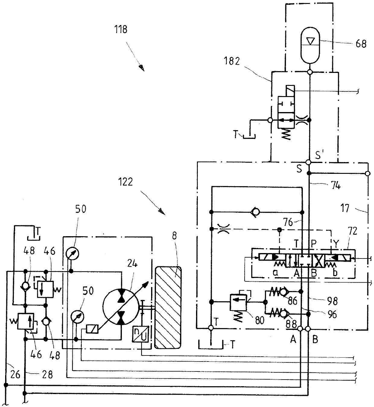
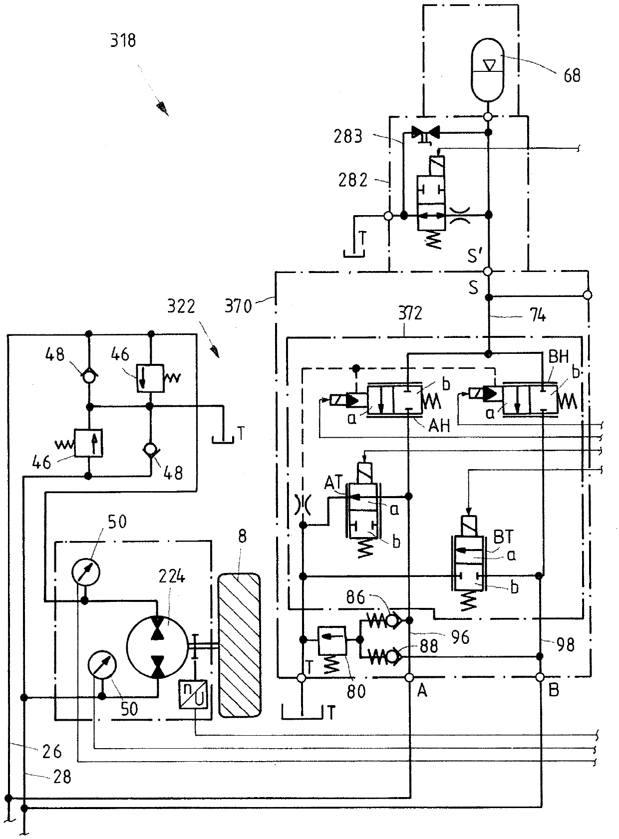
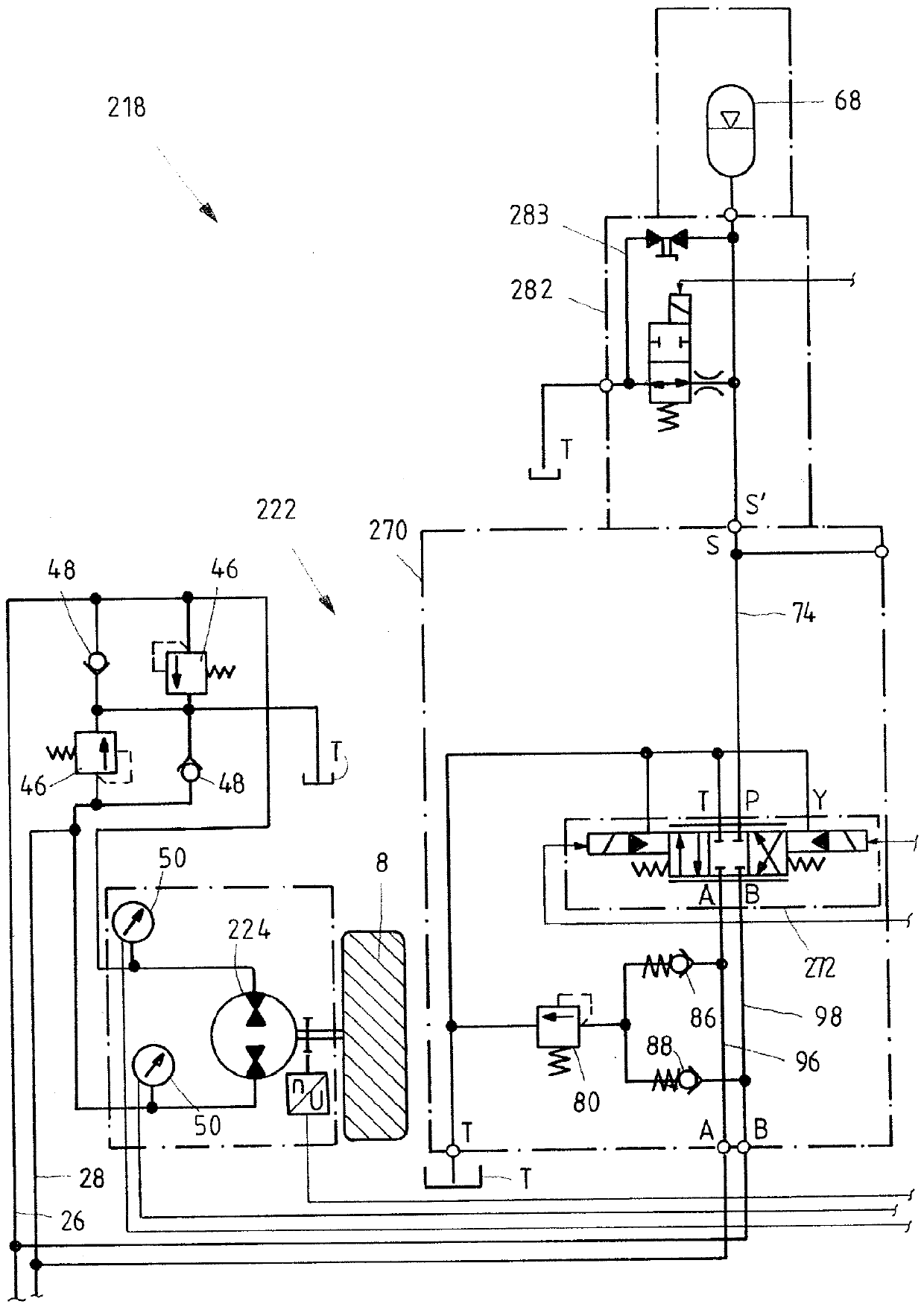
[0027] The rotation of the upper vehicle body 8 relative to the bottom vehicle body 6 is realized by hydraulic drive. The upper body 8 must be braked at the end of the rotation. In this case braking energy must be applied. In order to be able to store this braking energy for later use, solutions are known in which a hydraulic machine driven by the rotating upper body supplies pressure medium into the hydraulic accumulator. At a ...


PUM


Abstract

Disclosed is a hydrostatic drive for a slewing gear, especially for a mobile machine. The device comprises a first hydraulic machine coupled with the rotary drive. The first hydraulic machinein a normal operation can be supplied with a pressure medium by a hydraulic valve unit of an actuator. For a regenerative operation of the slewing gear, the drive has a hydraulic accumulator and a separately other hydraulic valve unit. The hydraulic accumulator from the first hydraulic machine with pressure medium is used for storing rotation or braking power of the slewing gear, and the first hydraulic machine from the hydraulic accumulator with hydraulic fluid is acted upon for recuperation of stored pressure fluid energy. Furthermore, the invention discloses a slewing gear and a mobile working machine with the slewing gear.

Description

technical field [0001] The invention relates to a hydrostatic drive for a swivel mechanism, in particular a movable working machine, a swivel mechanism with such a drive, and a movable working machine with such a swivel mechanism. Background technique [0002] Publication US 2014 / 0174069 A1 discloses a mobile working machine of the type, namely an excavator, with a corresponding hydrostatic drive of the type. In said publication, the slewing mechanism motor and other working devices are supplied by the main control valve unit arranged in the valve body using the pressure medium supplied to the pump. The swing mechanism motor moves the upper body of the excavator and can be driven in two directions of motion. During the braking of the rotational movement of the upper bodywork, there is the possibility that the hydraulic accumulator is supplied with pressure medium from the swing gear motor which subsequently switches into pump operation. In this way, the rotational or braki...

Claims


Application Information

Patent Timeline
Patent Type & Authority Patents(China)
IPC IPC(8): F15B11/08F15B21/12F15B1/033E02F9/22E02F9/12
CPCE02F9/123E02F9/128E02F9/2217F15B1/024F15B21/14F15B2211/212F15B2211/41581F15B2211/665F15B2211/6653F15B2211/7058F15B2211/7135
Inventor M.施坦格尔B.沃格林M.施蒂格勒
Owner ROBERT BOSCH GMBH
Why Eureka
Try Eureka