
Hydraulic tensioner for timing chain of engine

A technology of hydraulic tensioner and engine, applied in the direction of belt/chain/gear, mechanical equipment, transmission device, etc., to reduce the risk of abnormal chain system, simple structure and installation, and simplified design

Inactive Publication Date: 2014-03-26
CHONGQING CHANGAN AUTOMOBILE CO LTD
View PDF5 Cites 7 Cited by
  • Summary
  • Abstract
  • Description
  • Claims
  • Application Information

AI Technical Summary

Problems solved by technology

[0003] The traditional solution is to add a special secondary filter to the oil passage, which requires changing the design of the engine oil passage and adding a special part

Method used


Image

  • Hydraulic tensioner for timing chain of engine
  • Hydraulic tensioner for timing chain of engine
  • Hydraulic tensioner for timing chain of engine

Examples


Embodiment Construction

[0018] The present invention will be further described below in conjunction with the accompanying drawings.

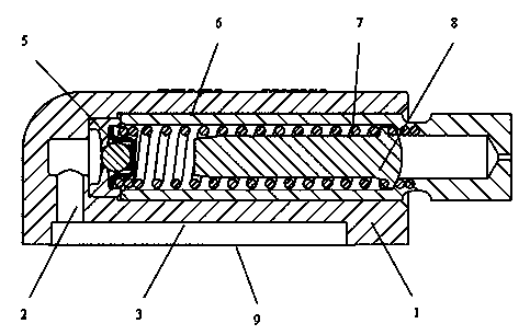
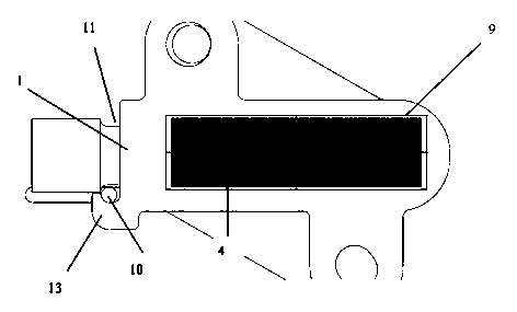
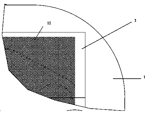
[0019] like figure 1 As shown, the tensioner is composed of a housing 1, a one-way valve 5, a piston 6, a spring 7, a plunger 8 and a metal filter 9, and the piston 6, spring 7 and plunger 8 are installed in the inner cavity of the housing 1 In 4, an oil storage chamber 3 is opened on one side of the housing 1, and the oil storage chamber 3 is connected to the inner cavity through the oil inlet hole 2, and the outside of the oil storage chamber is connected with the oil passage of the engine, and the metal filter screen 9 is covered on this side. The engine oil in the oil storage chamber 3 comes from the engine. Oil is introduced into the housing cavity 4 through the oil inlet hole 2 . The one-way valve 5 is arranged between the oil inlet hole 2 and the inner cavity 4 of the housing. When the oil pressure from the oil inlet hole 2 is greater than a certain value, th...


PUM


Abstract

Disclosed is a hydraulic tensioner for a timing chain of an engine. The tensioner comprises a casing. A piston mounted in an inner cavity of the casing is capable of moving in the cavity along with pressure of engine oil. A check valve for controlling the pressure of the engine oil is arranged in an oil inlet of the inner cavity. A pretension spring is arranged between the check valve and the piston, and contacts with the check valve and the piston through a plunger respectively. The hydraulic tensioner is characterized in that an oil storage cavity is formed on one side of the casing, one side of the oil storage cavity is connected with an oil channel of the engine, the other side of the oil storage cavity is communicated with the oil inlet of the inner cavity, and a metal filter screen is arranged on the side, connected with the oil channel of the engine, of the oil storage cavity. As the metal filter screen is added on the oil storage cavity of the tensioner, impurities of the limited diameter are blocked outside the tensioner under the filtering function of the metal filter screen, only impurities of the diameter smaller than the gap between the plunger of the tensioner and the casing of the tensioner can enter the engine oil in the tensioner, and jamming and failure of the tensioner are avoided.

Description

technical field [0001] The invention relates to a hydraulic tensioner used for tensioning a timing chain on an engine. Background technique [0002] The engine timing chain tensioner is a device used to prevent the timing chain from being worn out after long-term use, and the chain meshing abnormality and noise caused by excessive sag of the loose side. The traditional engine timing chain hydraulic tensioner (hereinafter referred to as the tensioner) itself has no structure to filter out oil impurities. The metal impurities in the engine and the oil can easily enter the tensioner, and the tensioner plunger and the tensioner The gap between the housings of the tensioner is very small. Once the diameter of metal impurities entering the tensioner is larger than the gap between the plunger and the housing of the tensioner, it may cause the piston to stick, the tensioning function will fail, and the timing chain system will fail. . [0003] The traditional solution is to add a ...

Claims


Application Information

Patent Timeline
Patent Type & Authority Applications(China)
IPC IPC(8): F16H7/08
CPCF16H7/0829F16H2007/0806F16H2007/0812F16H2007/0842F16H2007/0859
Inventor 李春余训蒋树徽朱玉明任志勇
Owner CHONGQING CHANGAN AUTOMOBILE CO LTD
Learn More