
Buffer type large-torque spring restoration executing mechanism

A spring return, actuator technology, applied in mechanical equipment, engine components, valve details, etc., can solve problems such as loss, easily damaged internal components, valve failure, etc., to increase comprehensive economic profits, prolong service life, and reduce excessive The effect of wear

Active Publication Date: 2014-03-26
WUXI SMART AUTO CONTROL ENG CO LTD
View PDF8 Cites 6 Cited by
  • Summary
  • Abstract
  • Description
  • Claims
  • Application Information

AI Technical Summary

Problems solved by technology

Small-sized control valves can no longer meet the ever-expanding production capacity demand, mainly manifested in the fact that the actuator structure of the control valve used to drive cannot fully meet the driving device of large-sized control valves through the design mode of proportional amplification.
Ordinary pneumatic rack-and-pinion actuators, pneumatic film-type quarter-turn actuators, and pneumatic piston-type quarter-turn actuators are widely used in rotary valves such as butterfly valves and ball valves. However, these actuators are often due to their structure and processing conditions. Due to the limitations of the valve, it cannot meet the valve requirements for frequent actions. It is easy to damage the internal components in the process of frequent actions, and even cause serious valve failures, so that the entire device is forced to stop for maintenance, which brings greater economic losses to customers.

Method used


Image

  • Buffer type large-torque spring restoration executing mechanism
  • Buffer type large-torque spring restoration executing mechanism

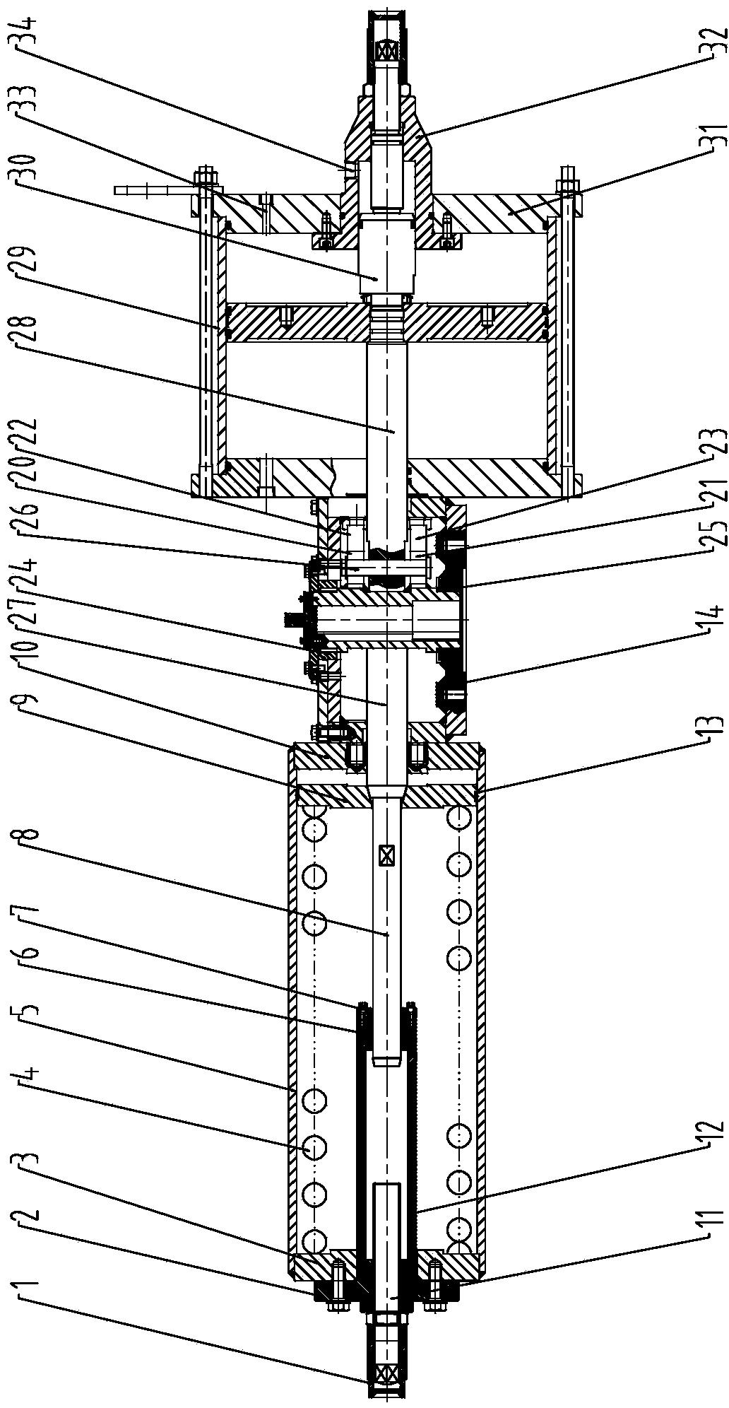
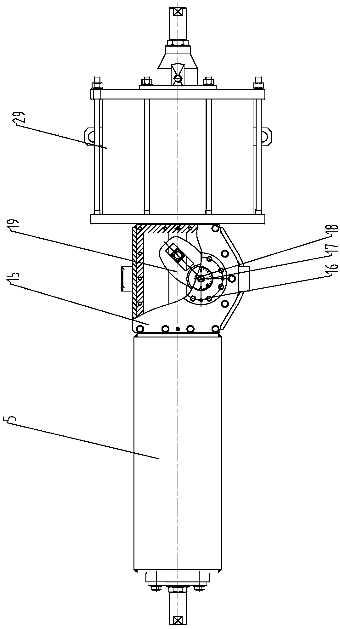
Examples


Embodiment Construction

[0023] Below the present invention will be further described in conjunction with the embodiment in the accompanying drawing:

[0024] Such as Figure 1~2 As shown, the present invention mainly comprises cylinder body 5, and left cylinder head 3 and right cylinder head 10 are welded respectively at two ends of cylinder body 5, and cylinder body 5 is provided with the resetting piston 9 that can slide left and right, resetting piston 9 and left cylinder head 3 A return spring 4 that compresses the return piston 9 is arranged between them. A guide belt 13 is provided on the connecting surface of the reset piston 9 with the cylinder body 5 , and the guide belt 13 guides the reset piston 9 .

[0025] The left cylinder head 3 outside is connected with the left cylinder head pressure plate 2 by bolts, and the cylinder body 5 is provided with a guide sleeve 12, and the guide sleeve 12 is pressed on the left cylinder head 3 by the left cylinder head pressure plate 2. The guide sleeve...


PUM


Abstract

The invention relates to a pneumatic executing mechanism, in particular to a buffer type large-torque spring restoration executing mechanism with a final position pneumatic buffer structure, and belongs to the technical field of pneumatic executing mechanisms. The buffer type large-torque spring restoration executing mechanism comprises a cylinder body. The outer side of a left cylinder cover is connected with a left cylinder cover pressing plate through bolts. A guide sleeve is disposed in the cylinder body. The guide sleeve is tightly pressed on the left cylinder cover through the left cylinder cover pressing plate. The right side of a right cylinder cover is connected with a converting box through bolts. The rear end of the converting box is connected with a buffer air chamber. The rear end of the buffer air chamber is connected with the rear cylinder cover of the buffer air chamber. A buffer seat is connected to the rear cylinder cover of the buffer air chamber. A buffer plunger is slidably mounted in the buffer seat. The buffer type large-torque spring restoration executing mechanism has the advantages that the drive requirements of a valve acting frequently can be satisfied, internal component damage, caused by frequent acting, of the executing mechanism can be avoided effectively, and accordingly maintenance frequency can be lowered, and economical benefits can be increased.

Description

technical field [0001] The invention relates to a pneumatic actuator, specifically a large-torque spring return type pneumatic actuator with an end position air buffer structure, belonging to the technical field of pneumatic actuators. Background technique [0002] Industrial automation production is rapidly replacing the traditional industrial production mode, becoming the main force to promote productivity and reduce labor intensity of workers. With the rapid expansion of production scale, the specifications and control accuracy of control valves have become important factors restricting the process of industrial automation. Small-sized control valves can no longer meet the ever-expanding production capacity demand, mainly manifested in the fact that the actuator structure of the control valve used to drive cannot fully meet the drive device of large-sized control valves through the design mode of proportional amplification. Ordinary pneumatic rack-and-pinion actuators, p...

Claims


Application Information

Patent Timeline
IPC IPC(8): F16K31/122F16K47/00
CPCF16K31/1221
Inventor 陈彦闵玉萍邹帆顾嘉
Owner WUXI SMART AUTO CONTROL ENG CO LTD
Learn More