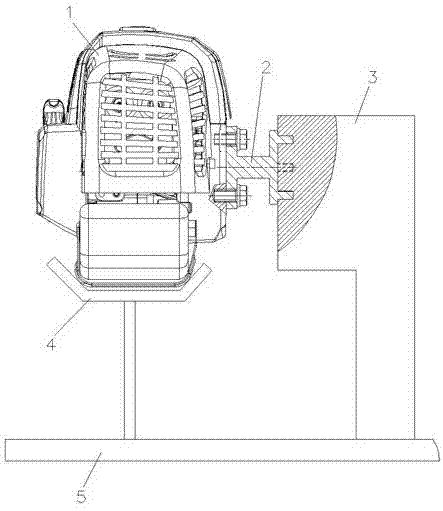
Connecting device for engine and dynamometer
A connecting device and a dynamometer technology, applied in the field of mechanical transmission, can solve the problems of difficulty in ensuring the neutrality of the connection between an engine 1 and a dynamometer 3, large error in test results, and high labor intensity, and achieve a simple structure and high reliability. Neutral and labor-intensive effects
- Summary
- Abstract
- Description
- Claims
- Application Information
AI Technical Summary
Problems solved by technology
Method used
Image

Examples
Embodiment Construction
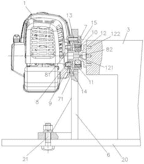
[0013] The present invention will be further described below with reference to the accompanying drawings and embodiments.
[0014] like figure 2 As shown, the present invention includes an L-shaped bracket 6, a support 7, an engine connecting seat 8, several nylon sleeves 9, a bearing 10 and a dynamometer connecting seat 12, and the L-shaped bracket 6 and the dynamometer 3 are respectively supported on a common base plate 20, the engine 1 and the dynamometer 3 are respectively located on both sides of the L-shaped bracket 6, and the bottom of the L-shaped bracket 6 is fixed on the common base plate 20 by two screw and nut groups 21. The left end flange 71 of the support is radially positioned in the inner hole of the upper end of the bracket 6, and the four fastening screws 13 respectively pass through the L-shaped bracket 6 and the left end flange 71 of the support, and connect the L-shaped bracket 6, the support 7 and the engine. 1 is connected into one. The two nylon sle...
PUM
 Abstract
Description
Claims
Application Information
 - R&D
- Intellectual Property
- Life Sciences
- Materials
- Tech Scout
- Unparalleled Data Quality
- Higher Quality Content
- 60% Fewer Hallucinations
Browse by: Latest US Patents, China's latest patents, Technical Efficacy Thesaurus, Application Domain, Technology Topic, Popular Technical Reports.
© 2025 PatSnap. All rights reserved.Legal|Privacy policy|Modern Slavery Act Transparency Statement|Sitemap|About US| Contact US: help@patsnap.com