Electrical switch system

An electrical switch, circuit switch technology, applied in electrical program control, program control in sequence/logic controllers, etc., can solve the problem of reducing system reliability and safety, normal operation interference of electrical equipment, power supply intolerable, etc. problems, to achieve the effect of saving standby power consumption, avoiding the possibility of being struck by lightning, and avoiding equipment aging.

Inactive Publication Date: 2014-03-26
冯晓东
View PDF12 Cites 5 Cited by
  • Summary
  • Abstract
  • Description
  • Claims
  • Application Information

AI Technical Summary

Problems solved by technology

This structure is relatively complex and costly
[0018] 2: The power supply connected to the main circuit cannot withstand high impulse voltage, which reduces the reliability and safety of the system
[0019] 3: The calculation of standby power consumption requires two sensors, voltage sensor and current sensor, which increases the system cost
When electrical equipment is working, its current always flows through this high-power metal sheet resistor, which will inevitably cause it to heat up, and its heat generation is proportiona...

Method used


Image

  • Electrical switch system
  • Electrical switch system
  • Electrical switch system

Examples


no. 1 example

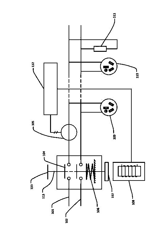
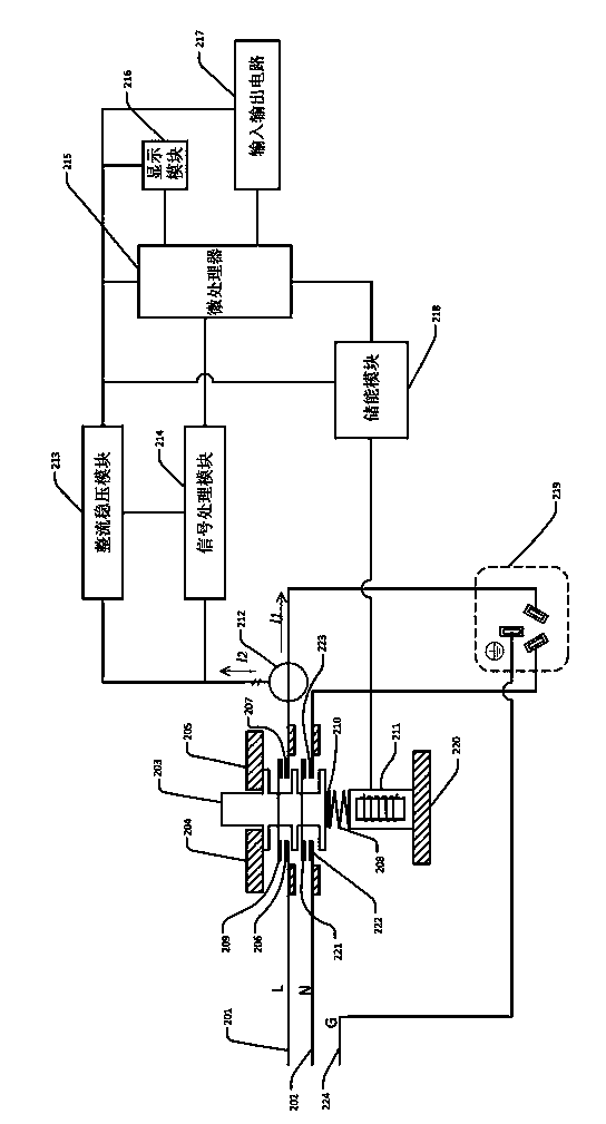
[0079] figure 2 The structure of a first embodiment of an electrical switching system is shown. The electrical switch system includes three major parts: circuit switch assembly, current transformer 212 and switch control circuit, wherein the circuit switch assembly is installed in the power supply lines 201, 202, and is connected to the electrical equipment on the power supply line (or socket 219). Keep the power supply line open during work.

[0080] The current transformer 212 is installed in the power supply lines 201 and 202, and no output current is generated when there is no current passing through the power supply lines. During the operation of the electrical equipment, the working current on the power supply lines passes through the current transformer, and the current transformer secondary The output induction current signal of the side is used as the input signal of the switch control circuit.

[0081] The switch control circuit is connected to the current transfo...


PUM


Abstract

The invention discloses an electrical switch system. According to the electrical switch system, the state of an electric device is judged by detecting current parameters, and corresponding operations are performed according to a result. The technical scheme is that the electrical switch system comprises a circuit switch component, a current transformer and a switch control circuit; the circuit switch component is mounted in a power supply circuit for allowing the power supply circuit to be conductive always in the working period of the electric device connected onto the power supply circuit; the current transformer is mounted in the power supply circuit, the current transformer does not produce output current when no current passes the power supply circuit, in the working period of the electric device, the working current on the power supply circuit passes the current transformer, and an output induced current signal on the secondary side of the current transformer is used as an input signal of the switch control circuit; the switch control circuit is connected with the current transformer for converting the input signal into a working power supply for internal circuit operation on one hand, and judging the working condition of the electric device on the power supply circuit according to the input signal on the other hand to perform control operation according to the working condition.

Description

technical field [0001] The present invention relates to electrical devices, and more particularly to electrical switching systems. Background technique [0002] In modern life, various electrical devices are increasingly used in the home as well as in commercial and industrial applications. Many times these electric devices are in a standby state and consume standby power. Although the standby power is usually much smaller than the normal power of the equipment, due to the huge number of electrical equipment and the long cumulative duration, the cumulative power consumption is still very considerable. [0003] According to relevant information, the standby power consumption in ordinary households is as follows: [0004] Table 1 [0005] [0006] Source: Meier & Lebot 2002. [0007] The share of standby power consumption in total household electricity consumption is as follows. [0008] Table 2 Estimation of Standby Power Consumption [0009] [0010] It can be se...

Claims


Application Information

Patent Timeline
IPC IPC(8): G05B19/04
Inventor 冯晓东
Owner 冯晓东
Why Eureka
Try Eureka