Electrode layout method of static formed film antenna

An electrostatic forming and layout method technology, applied in the direction of electrical digital data processing, special data processing applications, instruments, etc., can solve problems such as no positive solutions, and achieve the effect of reducing complexity

Active Publication Date: 2014-03-26
XIDIAN UNIV
View PDF2 Cites 24 Cited by
  • Summary
  • Abstract
  • Description
  • Claims
  • Application Information

AI Technical Summary

Problems solved by technology

However, the existing literature and related materials have not given a positive corresponding solution.

Method used


Image

  • Electrode layout method of static formed film antenna
  • Electrode layout method of static formed film antenna
  • Electrode layout method of static formed film antenna

Examples


Embodiment Construction

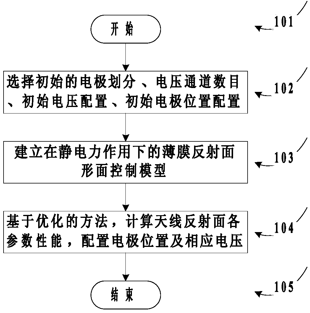
[0042] like figure 1 Shown, a kind of electrode layout method of electrostatic forming film antenna, it is characterized in that: comprise the steps:

[0043] Step 101: Start the electrostatic forming film reflector antenna electrode layout method;

[0044] Step 102: Select initial electrode division, number of voltage channels, initial voltage configuration, and initial electrode position configuration;

[0045] Step 103: Establishing a shape control model of the thin film reflective surface under the action of electrostatic force;

[0046] Step 104: Based on the optimization method, calculate the performance of each parameter of the antenna reflector, configure the electrode position and the corresponding voltage;

[0047] Step 105: End the antenna layout method of the electrostatically formed film reflector.

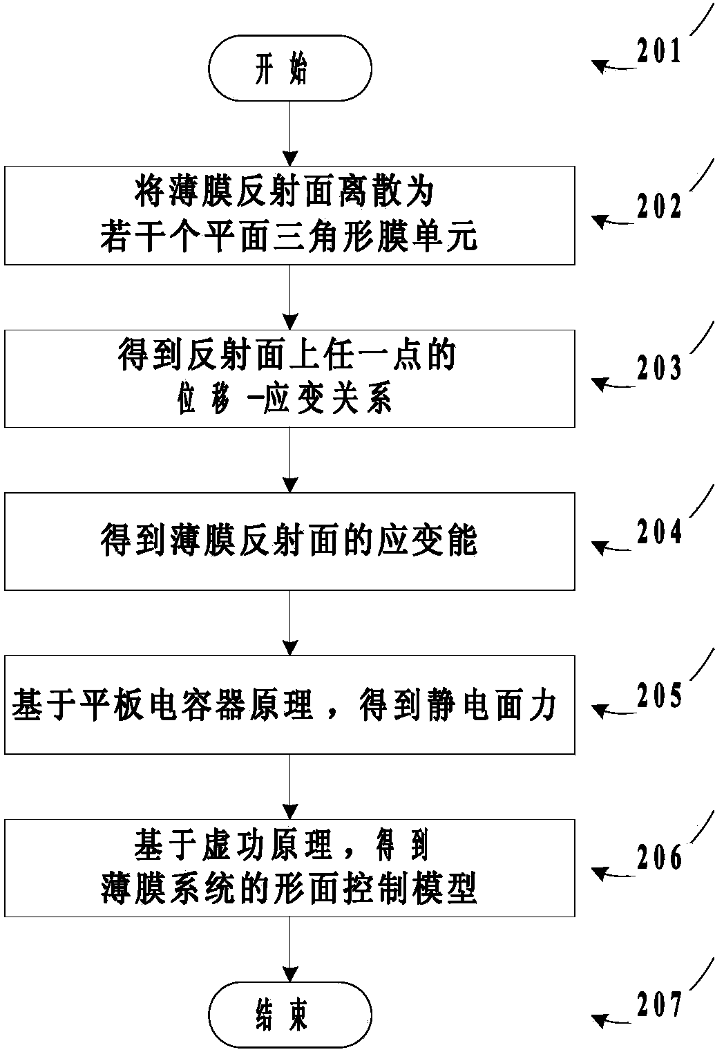
[0048] like figure 2 As shown, the described step 103 establishes the thin film reflective surface shape control model under the action of electrostatic force an...


PUM


Abstract

The invention aims at providing an electrode layout method of a static formed film antenna. A finite element model of a film reflecting face antenna is set up, corresponding optimal configuration are carried out on the position of an electrode and the voltage, thus the optimal electrode layout of the film reflecting face antenna is achieved. By means of the electrode layout method of the static formed film antenna, the face precision of a reflecting face can be effectively improved, wrinkling of the reflecting face is prevented and complexity of the system is relieved.

Description

technical field [0001] The invention relates to electrode layout and its application field, in particular to an electrode layout method of an electrostatically formed film antenna. Background technique [0002] Thin-film reflector antenna is a new idea to improve the accuracy of the reflective surface. On the basis of the mesh reflective surface, electrodes and thin-film reflective surfaces are placed on the cable net to make it a higher-precision antenna through the electrostatic field force. Reflective surface. The shape control of the reflective surface of the electrostatically formed film is mainly based on controlling the size and distribution of the potential on the electrode. The size of the electrostatic force on the film is related to the shape of the plate, the voltage and the shape of the film. Traditionally, the polar plate is made to be parallel to the final surface of the film, and the simple correspondence between the electrostatic field force and the electr...

Claims


Application Information

Patent Timeline
Patent Type & Authority Applications(China)
IPC IPC(8): G06F17/50
Inventor 张逸群段宝岩杜敬利杨东武高峰张树新刘超郝佳
Owner XIDIAN UNIV
Why Eureka
Try Eureka