High-voltage direct-current breaker topology
A DC circuit breaker, high-voltage DC technology, applied in the direction of circuits, electrical components, electrical switches, etc., can solve the problems of unable to turn off the current, large conduction loss, etc., and achieve the effects of low manufacturing difficulty, high reliability, and low cost
- Summary
- Abstract
- Description
- Claims
- Application Information
AI Technical Summary
Problems solved by technology
Method used
Image

Examples
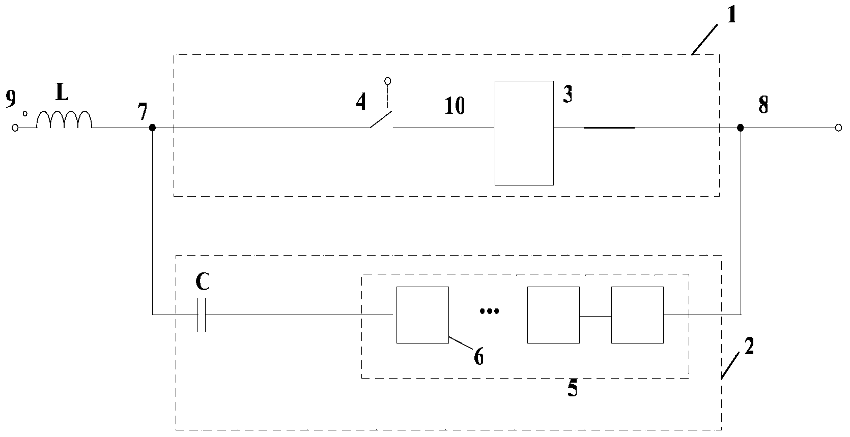
Embodiment 1
[0069] figure 2 Shown is embodiment 1 of the present invention, as figure 2 As shown, the voltage source 15 is a converter station, and the resistor 16 is a simulated short-circuit resistor. The basic topology of the present invention is composed of a first current path 1 and a second current path 2; the first lead-out terminal of the first current path 1 is connected with the first lead-out terminal of the second current path 2 as the first lead-out terminal of the DC circuit breaker It is connected to the DC transmission line 7 near the converter station side, and the second lead-out terminal of the first current path 1 and the second lead-out terminal of the second current path 2 serve as the second lead-out terminal of the DC circuit breaker and the connection between the second lead-out terminal of the far converter station side DC transmission line connection. The inductance L can be the inductance of the converter station itself, or the additional current-limiting i...
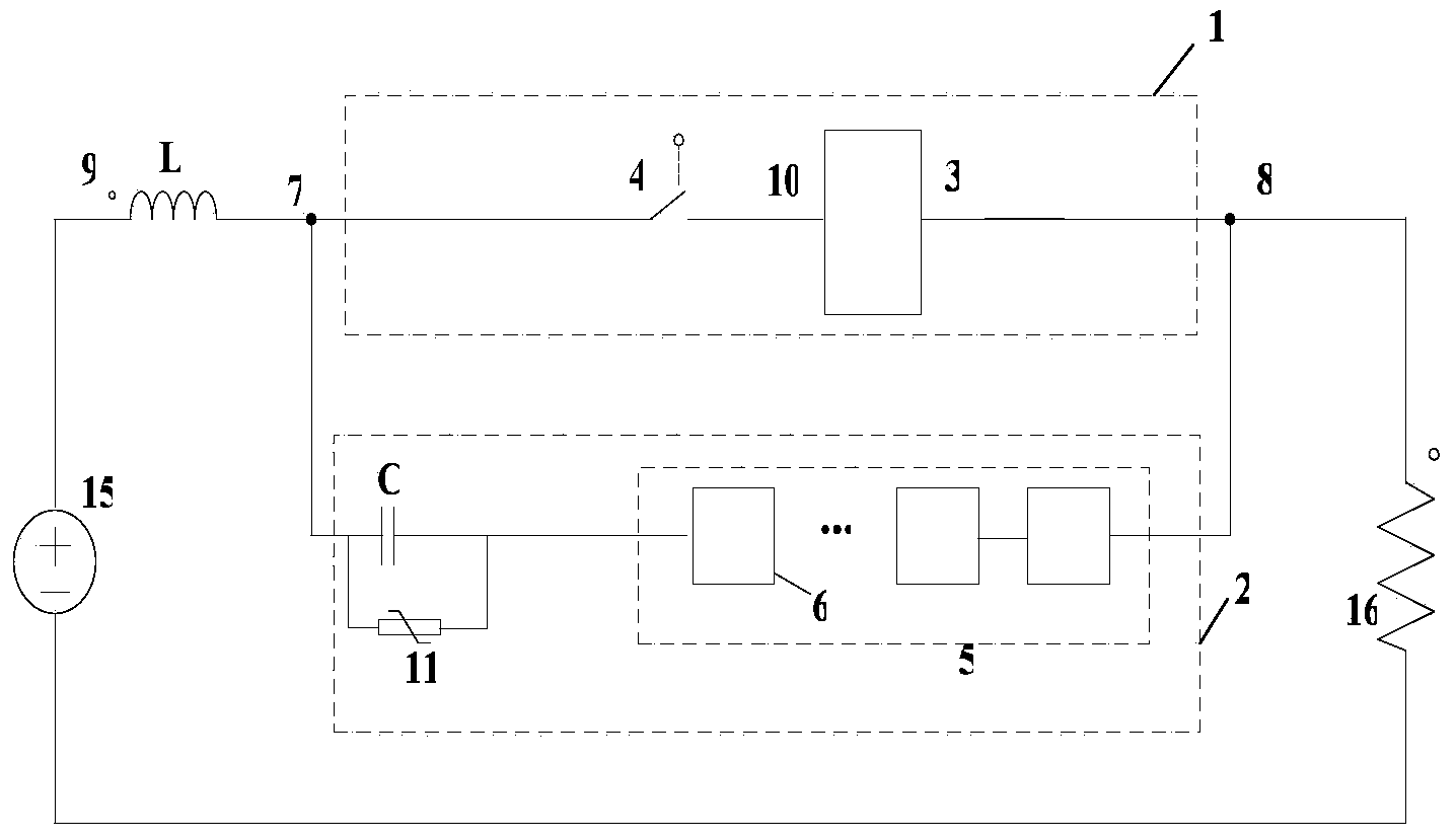
Embodiment 2
[0075] image 3 Shown is Example 2 of the present invention. image 3 Voltage limiters are connected in parallel at both ends of the first current path, both ends of the capacitor module of the second current path, and both ends of the cascaded capacitor sub-unit switching module. A voltage limiting device is connected in parallel between the first lead-out terminal of the first current path 1 and the ground, and between the second lead-out terminal of the first current path 1 and the ground, to protect various parts of the entire DC circuit breaker from overvoltage. It is also possible to selectively add voltage limiting devices at both ends of the place where protection is required.
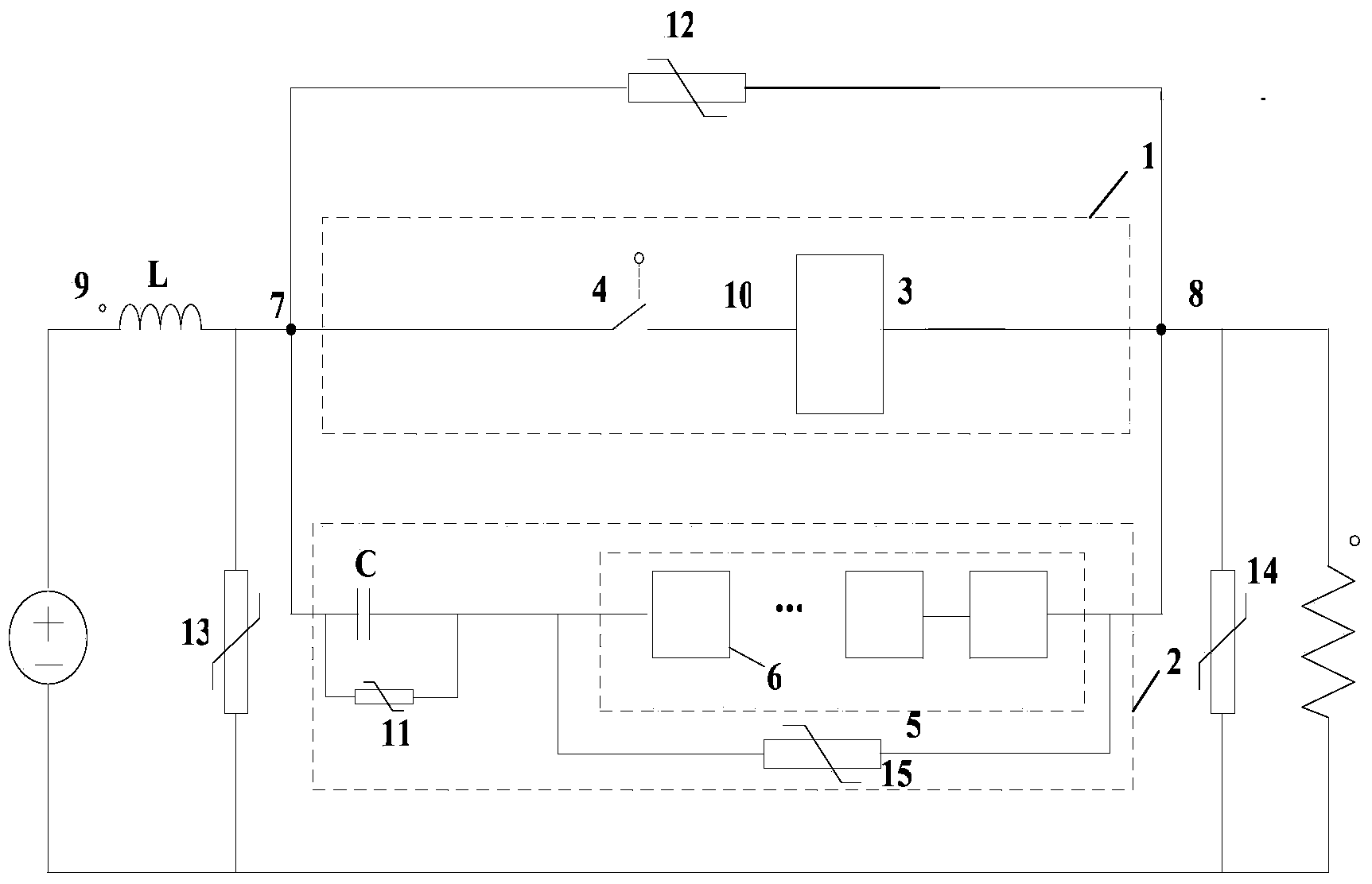
Embodiment 3
[0077] Figure 4 Shown is Example 3 of the present invention. Figure 4 The power electronic switch module 3 in the first current path 1 adopts a semi-controlled device thyristor. The power electronic switch module 3 can also be composed of multiple thyristors connected in series. In this way, the conduction loss of the entire DC circuit breaker is lower when the DC grid is operating normally, but since the thyristor has no self-shutoff capability, it is necessary to create a current zero-crossing point to turn it off. Therefore, in this embodiment, a pre-charging circuit is added at both ends of the capacitor unit C in the second current path, and the charging voltage is negative at the side near the converter station and positive at the side far from the converter station. After the line short-circuit fault is detected, the subunit full-control device groups of the cascaded capacitor subunit switching module 5 of the second current path 2 are turned on, and the capacitor u...
PUM
 Abstract
Description
Claims
Application Information