
An arc-extinguishing type current-limiting fuse

A fuse and current-limiting technology, applied in the direction of electrical components, circuits, emergency protection devices, etc., can solve problems such as large arcs, circuit system damage to equipment, etc., achieve low cost, easy maintenance, and facilitate popularization and application.

Inactive Publication Date: 2016-05-04
广西和谐电力科技有限公司
View PDF4 Cites 0 Cited by
  • Summary
  • Abstract
  • Description
  • Claims
  • Application Information

AI Technical Summary

Problems solved by technology

[0003] However, in practical applications, when overload or short circuit occurs, a large arc will be generated when the fuse is blown, and the burning of the arc will have a negative impact on the circuit system and damage the equipment.

Method used


Image

  • An arc-extinguishing type current-limiting fuse
  • An arc-extinguishing type current-limiting fuse

Examples


Embodiment 1

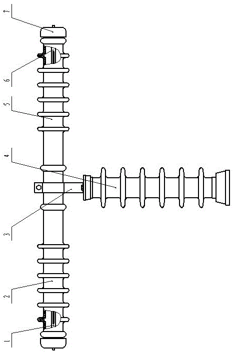
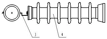
[0021] Such as figure 1 , figure 2 As shown, the present invention includes a left insulating porcelain bottle 2 and a right insulating porcelain bottle 5, the left insulating porcelain bottle 2 is provided with a left melt pipe 1, the right insulating porcelain bottle 5 is provided with a right melt pipe 6, the left melt pipe 1 and the right melting pipe Fuses are provided in the body tube 6, and one end of the left insulating porcelain bottle 2 and the right insulating porcelain bottle 5 are connected through a fastening flange 3, and one end of the fastening flange 3 is connected with the rod-shaped pillar 4, and the left melt pipe 1 and the right melting pipe One end of the body tube 6 is connected to each other, and the other end is respectively connected to the left insulating porcelain bottle 2 and the right insulating porcelain bottle 5 through the terminal cap 7, and the left melt pipe 1 and the right melt pipe 6 are radially provided with narrow slits.

[0022] In ...

Embodiment 2

[0024] The difference from Embodiment 1 is that the slits are rectangular, the direction is parallel to the axial directions of the left melt pipe 1 and the right melt pipe 6, and the number of slits is one.

[0025] In this embodiment, since the narrow slit is rectangular and its direction is parallel to the axial directions of the left melt pipe 1 and the right melt pipe 6, the arc of the fuse blown is more likely to occur in the narrow slit, and the arc extinguishing effect is better.

Embodiment 3

[0027] The difference from Embodiment 2 is that the two ends of the fastening flange 3 are respectively fixed by screws.

[0028] In this embodiment, the fastening flange 3 is disassembled by screws, so that the left insulating porcelain bottle 2 and the right insulating porcelain bottle 5 can be quickly disassembled, and it is more convenient to replace the fuse.


PUM


Abstract

The invention discloses an arc extinction type current-limiting fuse protector which is good in arc extinction effect, simple in structure and easy and convenient to maintain. The extinction type current-limiting fuse protector comprises a left porcelain insulator and a right porcelain insulator. A left fusant pipe is arranged in the left porcelain insulator, a right fusant pipe is arranged in the right porcelain insulator, fuse wires are arranged in the left fusant pipe and the right fusant pipe, one end of the left porcelain insulator is connected with one end of the right porcelain insulator through a fastening flange, one end of the fastening flange is connected with a rod-shaped supporting column, one end of the left fusant pipe is connected with one end of the right fusant pipe, the other end of the left fusant pipe and the other end of the right fusant pipe are connected with the left porcelain insulator and the right porcelain insulator through wiring end caps, and the left fusant pipe and the right fusant pipe are provided with narrow slits in the radial direction. The arc extinction type current-limiting fuse protector has the function of rapid extinction of electric arc generated due to fusing of the fuse wires in overload or short out.

Description

technical field [0001] The invention relates to a fuse, in particular to a current-limiting fuse with the function of quickly extinguishing the arc of the fuse. Background technique [0002] A fuse is a type of overcurrent protector. The fuse is mainly composed of melt, fuse tube and external filler. When in use, connect the fuse in series in the protected circuit. When the current of the protected circuit exceeds the specified value, and after a certain period of time, the heat generated by the melt itself will fuse the fuse and disconnect the circuit, thereby protecting the fuse. effect. The electrical appliances that use metal conductors as the melt to break the circuit are connected in series in the circuit. When the overload or short-circuit current passes through the melt, the melt itself will generate heat and fuse, thus playing a role in the power system, various electrical equipment and household appliances. Certain protective effect. With anti-delay characteris...

Claims


Application Information

Patent Timeline
Patent Type & Authority Patents(China)
IPC IPC(8): H01H85/38H01H85/17H01H85/175
Inventor 朱济伟黎国勇郭明光王庭松林时华黄秋金
Owner 广西和谐电力科技有限公司
Learn More