Turnover mechanism used for transmission line

A technology of overturning mechanism and transmission line, applied in the direction of conveyor objects, transportation and packaging, electrical components, etc., can solve the problems of low efficiency, waste of labor, unfavorable large-scale industrial production, etc., achieve stable operation and overturn, compact structure, meet The effect of the flip action request

Active Publication Date: 2014-03-26
BEIJING NAURA MICROELECTRONICS EQUIP CO LTD
View PDF4 Cites 9 Cited by
  • Summary
  • Abstract
  • Description
  • Claims
  • Application Information

AI Technical Summary

Problems solved by technology

[0008] The purpose of the present invention is to solve the problem that the existing silicon wafers are transported in two ways of stacking or slotting to load

Method used


Image

  • Turnover mechanism used for transmission line
  • Turnover mechanism used for transmission line
  • Turnover mechanism used for transmission line

Examples


Embodiment 1

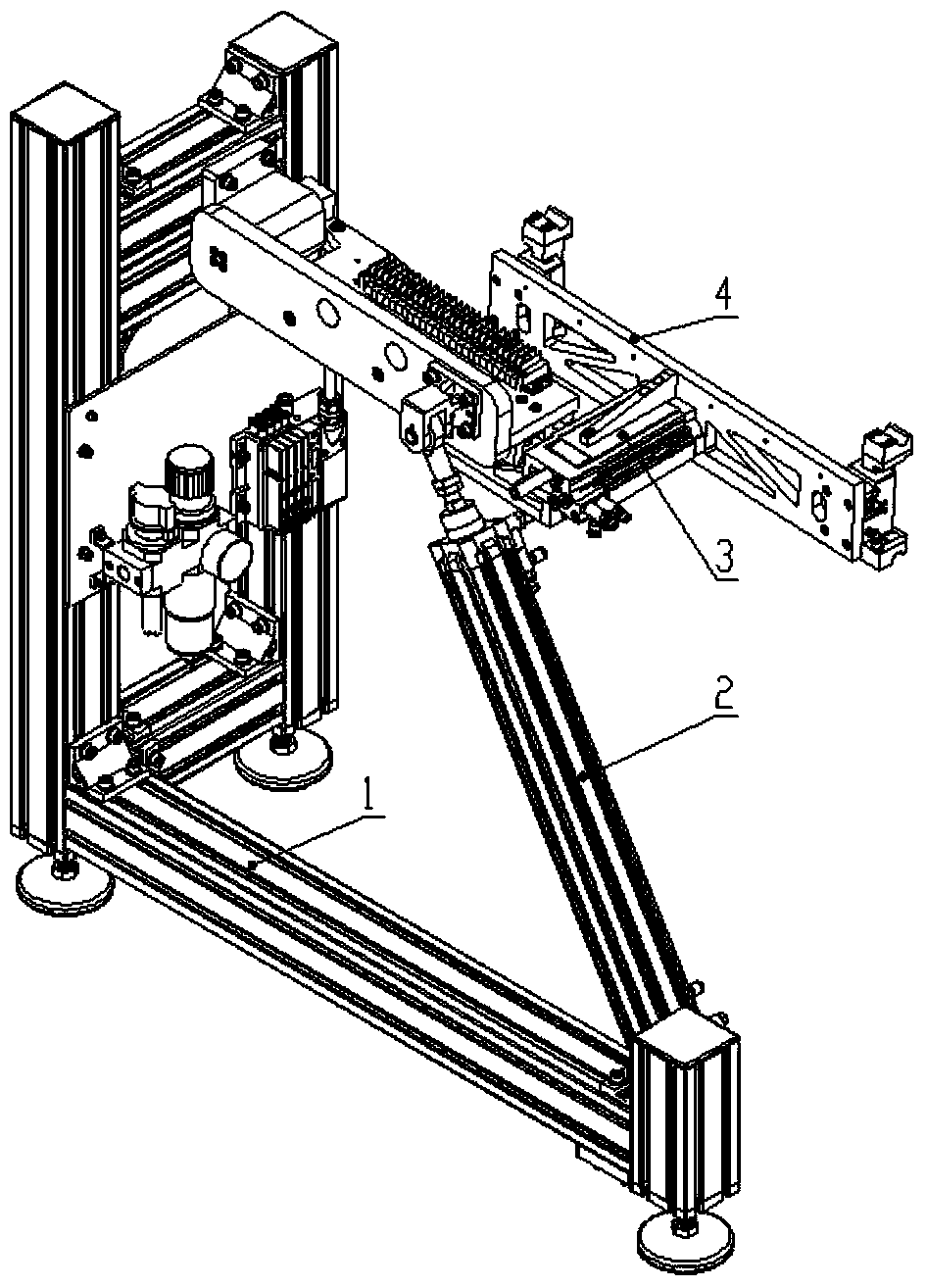
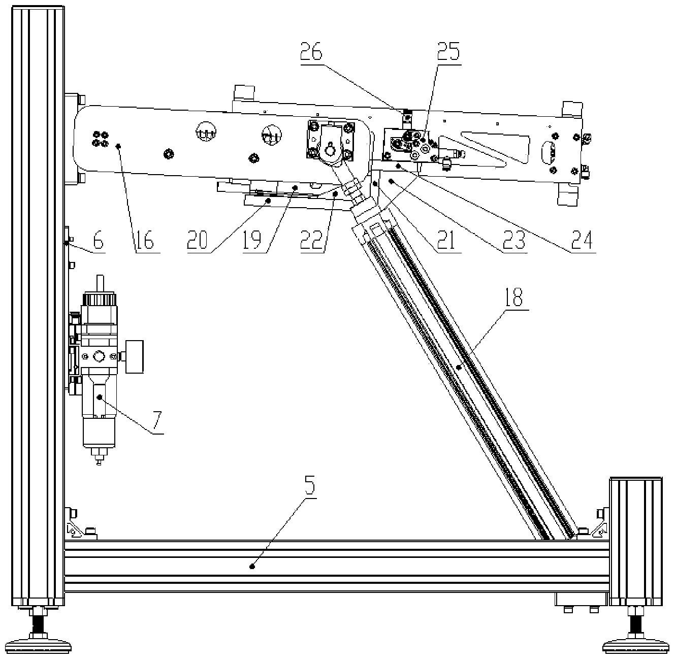
[0035] Such as figure 1 As shown, the embodiment of the present invention provides a turning mechanism used on the transmission line, which includes a main frame support unit 1, a turning unit 2, an orthogonal motion unit 3, a grabbing unit 4 and a control unit, and the main frame supports The unit 1 includes an overall frame 5 and a first mounting plate 6, the first mounting plate 6 is vertical and connected to one end of the overall frame 5; a control unit is fixedly connected to the first mounting plate 6, and the control unit is located at the second A central and lower position on the mounting plate 6, the control unit is used to control the retraction and extension of the standard cylinder 18, the first cylinder 19 and the second cylinder.

[0036] One end of the integral frame 5 away from the first mounting plate 6 is fixedly connected with a second mounting plate 17, and the second mounting plate 17 is fastened on one side of the integral frame 5 with fasteners, and th...


PUM


Abstract

The invention relates to a turnover mechanism used for a transmission line. The turnover mechanism used for the transmission line comprises a body frame supporting unit, a turnover unit, an orthogonal movement unit, a grabbing unit and a control unit. The body frame support unit comprises an integrated frame and a first mounting plate, and the first mounting plate is perpendicular to and connected to one end of the integrated frame. The first mounting plate is fixedly connected with the control unit. One end, away from the first mounting plate, of the integrated frame is fixedly connected with a second mounting plate, the second mounting plate is fixedly connected to the turnover unit, and the two ends of the orthogonal movement unit are connected to the turnover unit and the grabbing unit respectively. The turnover mechanism used for the transmission line has the advantages that through the effective matching of the turnover unit, the orthogonal movement unit and the grabbing unit, the fact that a material frame can be turned over between a vertical state and a horizontal state freely when the material frame enters different kinds of equipment is achieved, and the turnover mechanism used for the transmission line is compact in structure, stable in turning over and capable of achieving online work, and meets the turnover motion requirements of the silicon wafer material frame of a crystalline silicon solar automation line.

Description

technical field [0001] The invention relates to the technical field of logistics transmission of crystalline silicon solar energy automatic systems, in particular to a turning mechanism used on a transmission line. Background technique [0002] With the increasingly serious global warming effect and the depletion of oil, natural gas and coal, environmental protection and energy saving have become the theme of world development. As a renewable energy with unlimited reserves, clean and safe, solar energy is the development direction of new energy in the world. Under the guidance of the national new energy and renewable energy industry policy and driven by the strong demand in the European and American solar energy markets, the domestic solar photovoltaic industry has developed rapidly in recent years. At present, China has become a major solar cell manufacturing country, with the largest number of solar cell manufacturers and more than half of the production capacity in the w...

Claims


Application Information

Patent Timeline
IPC IPC(8): H01L21/677
CPCH01L21/67778
Inventor 李广旭刘珍妮徐现飞李补忠王广明桂晓波
Owner BEIJING NAURA MICROELECTRONICS EQUIP CO LTD
Why Eureka
Try Eureka