a turning mechanism

A technology of overturning mechanism and overturning bracket, which is applied in the direction of conveyor objects, transportation and packaging, etc., which can solve the problems of unfavorable large-scale production, and achieve the effect of meeting the requirements of overturning action, stable overturning and convenient control

Active Publication Date: 2016-02-17
BEIJING NAURA MICROELECTRONICS EQUIP CO LTD
View PDF6 Cites 0 Cited by
  • Summary
  • Abstract
  • Description
  • Claims
  • Application Information

AI Technical Summary

Problems solved by technology

[0003] At present, stacked and slotted material racks are used to load silicon wafers between the process units of the domestic crystalline silicon solar cell production line, which is not conducive to large-scale production through manual handling

Method used


Image

  • a turning mechanism
  • a turning mechanism
  • a turning mechanism

Examples


Embodiment Construction

[0031] The specific implementation manners of the present invention will be further described in detail below in conjunction with the accompanying drawings and examples. The following examples are used to illustrate the present invention, but are not intended to limit the scope of the present invention.

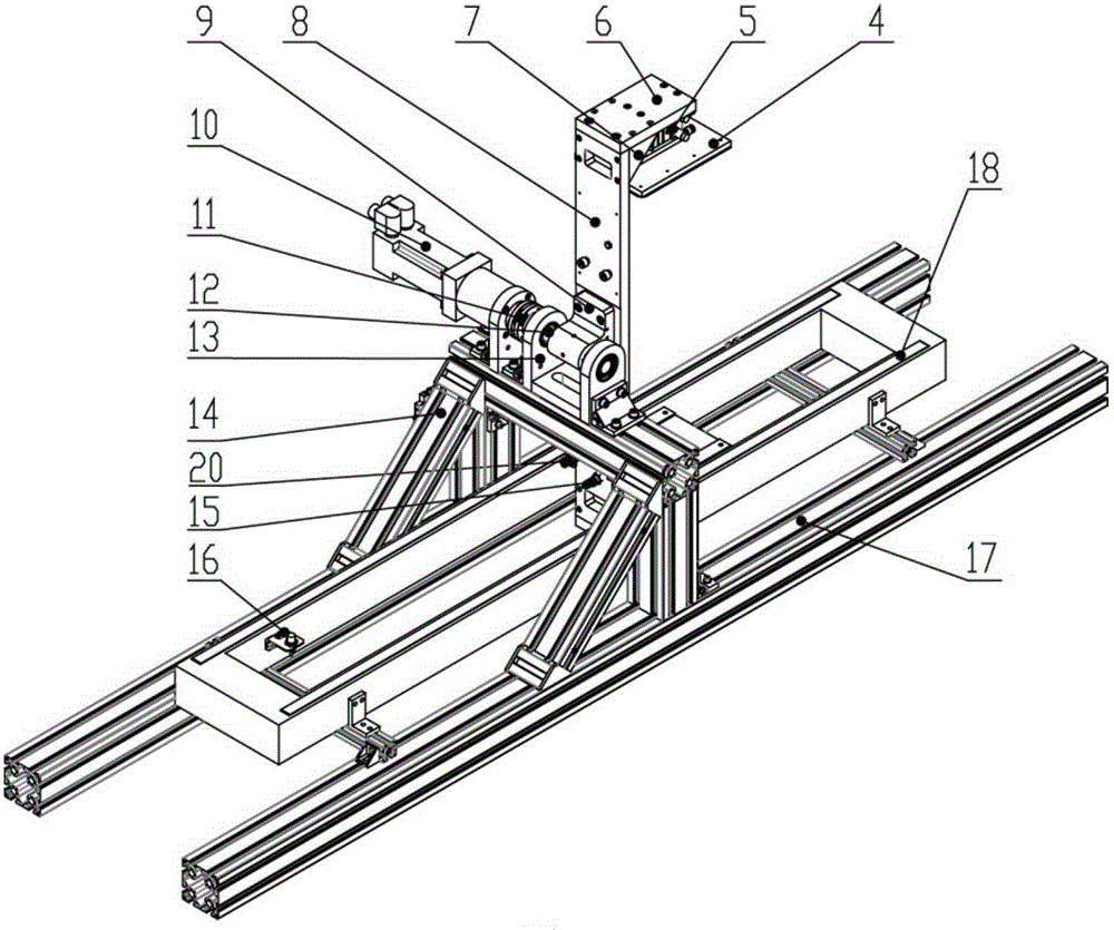
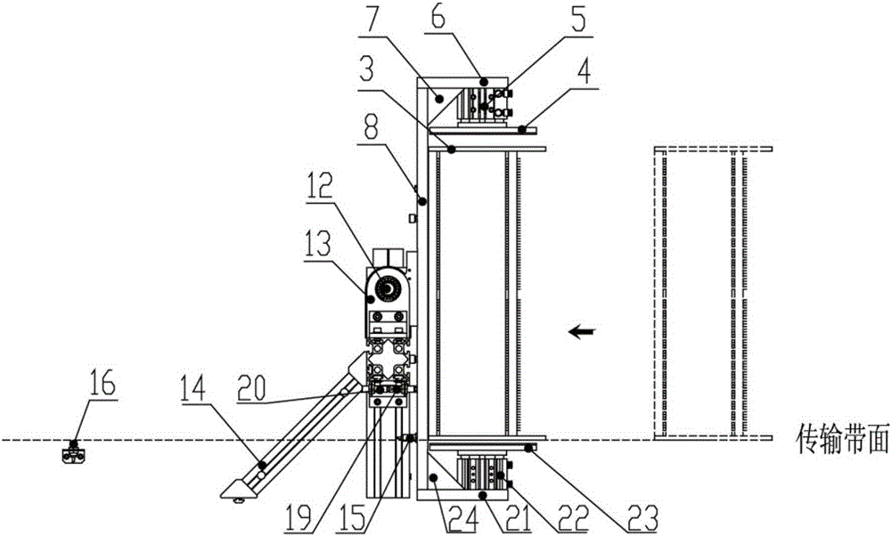
[0032] like figure 2 As shown, the turning mechanism of the present invention includes a transmission unit, a clamping unit and a turning unit, and each unit is connected to the control system and controlled by the control system.

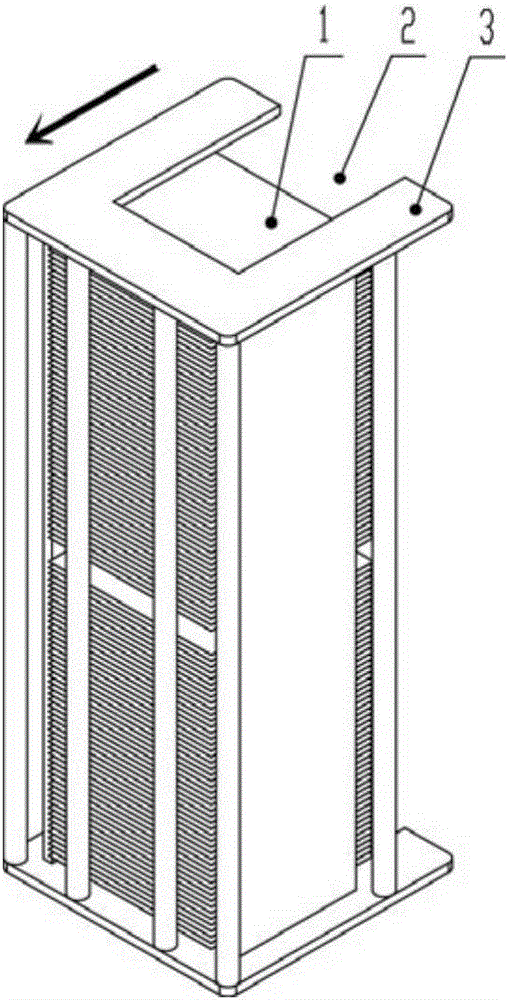
[0033] The transfer unit includes a transfer bracket 17 and a rack transfer belt 18, and is mainly responsible for the incoming and outgoing of the rack 3. The material rack conveying belt 18 will pass the material rack 3 into the clamping unit, and then pass out through the material rack conveying belt 18 after being overturned by the overturning unit. Before the material rack 3 enters the transfer unit, it must be ensured that the material ra...


PUM


Abstract

The invention relates to the field of crystalline silicon solar automatic line transmission, in particular to a turnover mechanism in the crystalline silicon solar automatic line transmission. The turnover mechanism comprises a transmission unit, a clamping unit and a turnover unit. The transmission unit in charge of transmitting a rack in and out comprises a rack transmission belt and a transmission support and is located under the turnover unit. The clamping unit in charge of clamping the rack comprises cylinder fixing frames, at least two air cylinders and cylinder push plates corresponding to the air cylinders and connected with the turnover unit. The turnover unit is in charge of turnover of the rack and comprises a turnover driving device and a turnover support. Through flexible clamping and stable turnover, the turnover process of the rack is realized on a transmission line under the premise of not damaging a silicon wafer, changing the direction of a process face of the silicon wafer is realized, and turnover action requirements of the crystalline silicon solar automatic line silicon wafer rack are met; the turnover mechanism is simple in structure, small in size, capable of being flexibly disposed on the transmission line, convenient to control and stable in turnover.

Description

technical field [0001] The invention relates to the field of automatic line transmission of crystalline silicon solar energy, in particular to a turning mechanism in automatic line transmission of crystalline silicon solar energy. Background technique [0002] With the increasingly serious global warming effect and the depletion of oil, natural gas and coal, environmental protection and energy saving have become the theme of world development. As a renewable resource with unlimited reserves, solar energy is undoubtedly environmentally friendly and is the development direction of new global energy. In recent years, the domestic solar photovoltaic industry has developed rapidly. This has greatly promoted the development of the domestic solar photovoltaic manufacturing equipment industry. With the rapid development of the industry, improving product quality and production efficiency and reducing production costs are the development direction of the solar photovoltaic industry...

Claims


Application Information

Patent Timeline
Patent Type & Authority Patents(China)
IPC IPC(8): B65G47/252
Inventor 李广旭陈志兵李圆晨李补忠王广明
Owner BEIJING NAURA MICROELECTRONICS EQUIP CO LTD
Why Eureka
Try Eureka