
Cleaning device in indirect air cooling tower

A technology for cleaning devices and air cooling towers, which is applied to cleaning heat transfer devices, flushing, lighting and heating equipment, etc. It can solve the problems of long cleaning cycle, high work intensity, and heavy structure, so as to improve cleaning quality and efficiency, and increase power generation Efficiency, the effect of improving cleaning efficiency

Active Publication Date: 2011-12-21
江苏科能电力机械有限公司
View PDF5 Cites 10 Cited by
  • Summary
  • Abstract
  • Description
  • Claims
  • Application Information

AI Technical Summary

Problems solved by technology

At present, this kind of supporting cleaning equipment usually has the following defects: the structure is relatively heavy, it is inconvenient to walk, and the operability is poor; The distance reaches 1.5m, the cleaning effect is extremely poor, and the innermost part cannot be cleaned at all; the cleaning pressure of the equipment design is low, the water volume is insufficient, the distance is too far, the cleaning angle is not suitable, and the self-weight of the equipment is large; it is generally manual operation, the environment is harsh, and the cleaning cycle long, overworked

Method used


Image

  • Cleaning device in indirect air cooling tower
  • Cleaning device in indirect air cooling tower
  • Cleaning device in indirect air cooling tower

Examples


Embodiment Construction

[0045] The following examples are used to illustrate the present invention, but are not intended to limit the scope of the present invention.

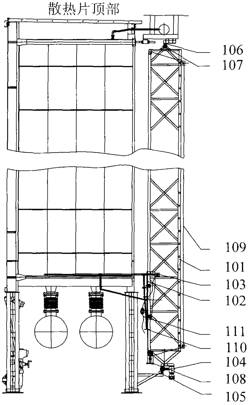
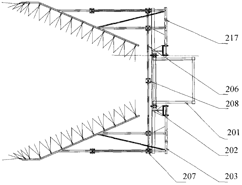
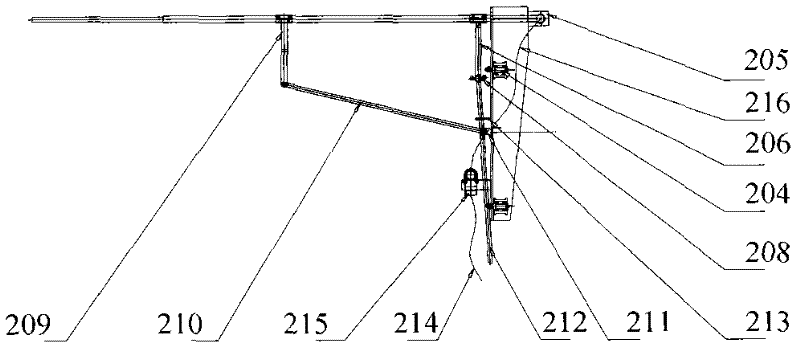
[0046] figure 1 It is a schematic diagram of the overall structure of the cleaning device in the indirect air-cooling tower of the present invention. As shown in the figure, the cleaning device in the indirect air-cooling tower of this embodiment includes a cleaning ladder 101, a transverse traveling mechanism, a nozzle tray 103, a longitudinal traveling mechanism and a cleaning pipe road. Among them, the horizontal walking mechanism is self-driven by the lower rail; the longitudinal walking mechanism includes a walking trolley 102 and a lifting drive 108, the nozzle frame 103 is fixed on the walking trolley 102, and the walking trolley 102 moves up and down on the cleaning ladder 101 through the lifting drive 108. Self-propelled; the nozzle tray 103 is arranged in a surrounding triangle, and it extends into the triangular unit formed...


PUM


Abstract

The invention relates to a cleaning device in an indirect air cooling tower. The device comprises a cleaning crawling ladder, a horizontal walking mechanism, a nozzle plate support, a longitudinal walking mechanism and a cleaning pipeline. For the cleaning device in the indirect air cooling tower provided by the technical scheme of the invention, aiming at the typical working environment of the indirect cold cleaning (such as the frontage of a triangle tube bundle is provided with obstructs of a louver window, a lacing bar and the like), the up and down walking cleaning of a surrounding nozzle plate in the tower replaces the original three-rack-pipe louver window external cleaning mode out of the tower, thus the cleaning quality and efficiency are improved, the heat radiation efficiency of the tube bundle is improved, the power generation efficiency is improved, and at the same time, the operation and maintenance cost of the device is lowered.

Description

technical field [0001] The invention relates to the technical field of indirect air cooling, in particular to a cleaning device in an indirect air cooling tower. Background technique [0002] As an effective measure to solve the waste of water resources in the process of power generation and the problem of building power plants in water-scarce areas, air-cooling technology has been widely used in China. At present, the air cooling technology used in my country is mainly two kinds of direct air cooling system (ACC) and indirect air cooling system (IDCT). The direct air cooling system uses the fan below the A-type tower to exchange heat for the fins of the tube bundle, and the air volume of the air supply can be controlled by the fan; while the indirect air cooling system uses a natural ventilation cooling tower, which is formed by the rise of hot air in the tower. The pressure difference drives the air around the bottom of the tower to flow into the tower to achieve the purp...

Claims


Application Information

Patent Timeline
Patent Type & Authority Applications(China)
IPC IPC(8): F28G9/00F28G15/04
Inventor 王科远李锦松
Owner 江苏科能电力机械有限公司
Learn More