
wireless communication device

A wireless communication device and antenna technology, which is applied to antenna supports/installation devices, devices that enable antennas to work in different frequency bands at the same time, antennas, etc., can solve problems such as resonant frequency offset, affecting signal transmission and reception performance, etc.

Inactive Publication Date: 2018-05-11
SHENZHEN FUTAIHONG PRECISION IND CO LTD
View PDF5 Cites 0 Cited by
  • Summary
  • Abstract
  • Description
  • Claims
  • Application Information

AI Technical Summary

Problems solved by technology

However, when the antenna needs to change its installation position, or needs to apply the antenna to other wireless communication devices, the resonant frequency of the antenna will inevitably shift due to changes in the environment around the antenna, which will affect the transmission and reception performance of the signal

Method used


Image

  • wireless communication device
  • wireless communication device
  • wireless communication device

Examples


Embodiment Construction

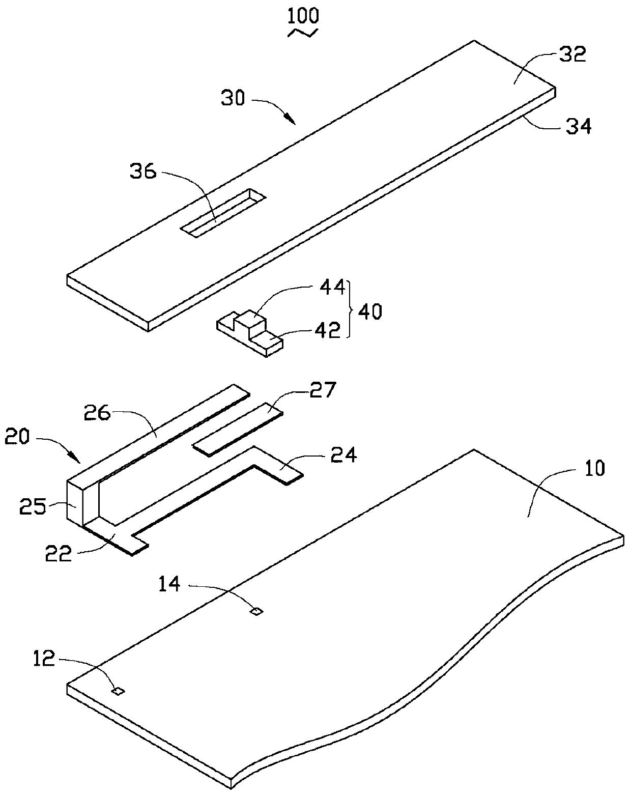
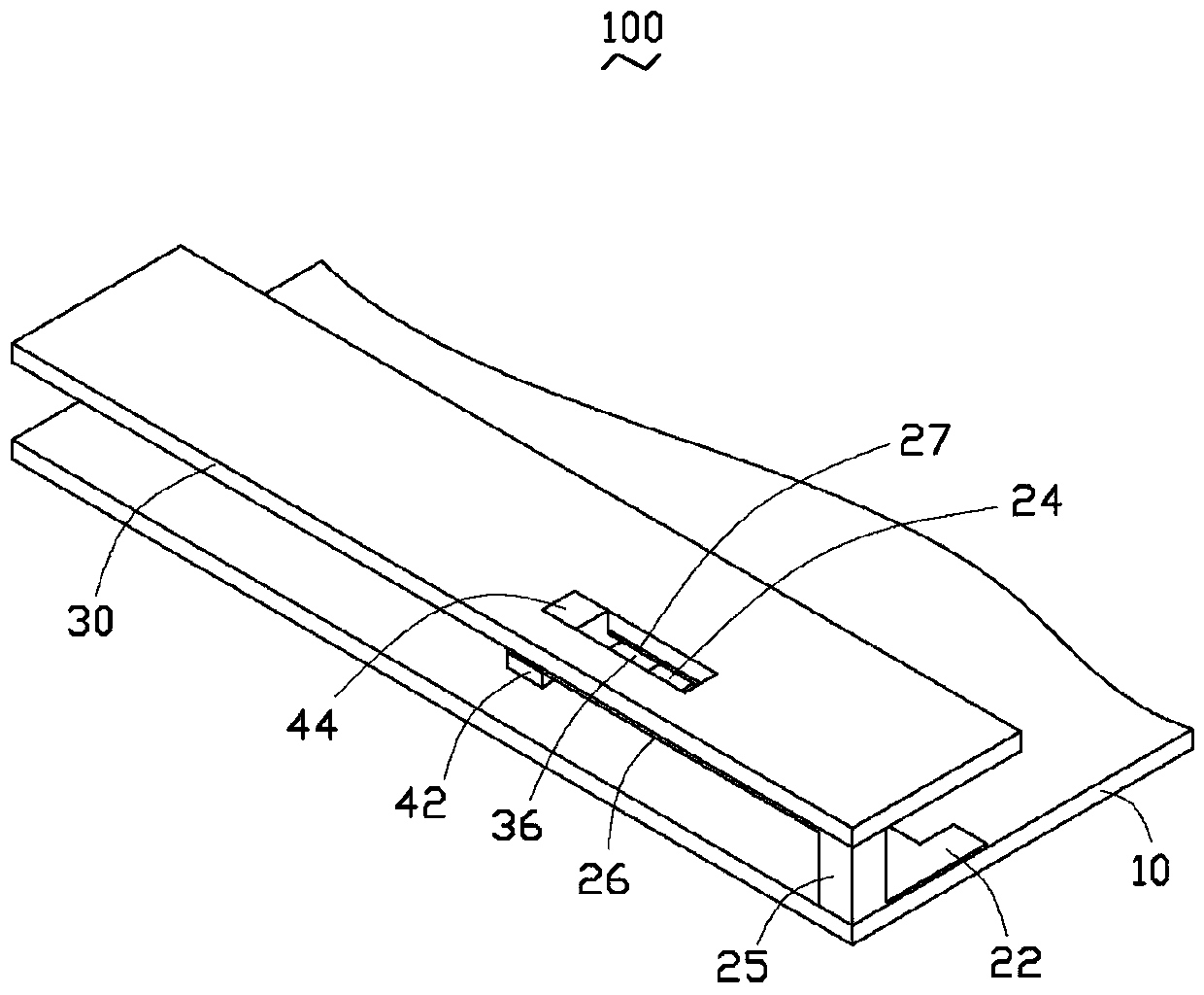
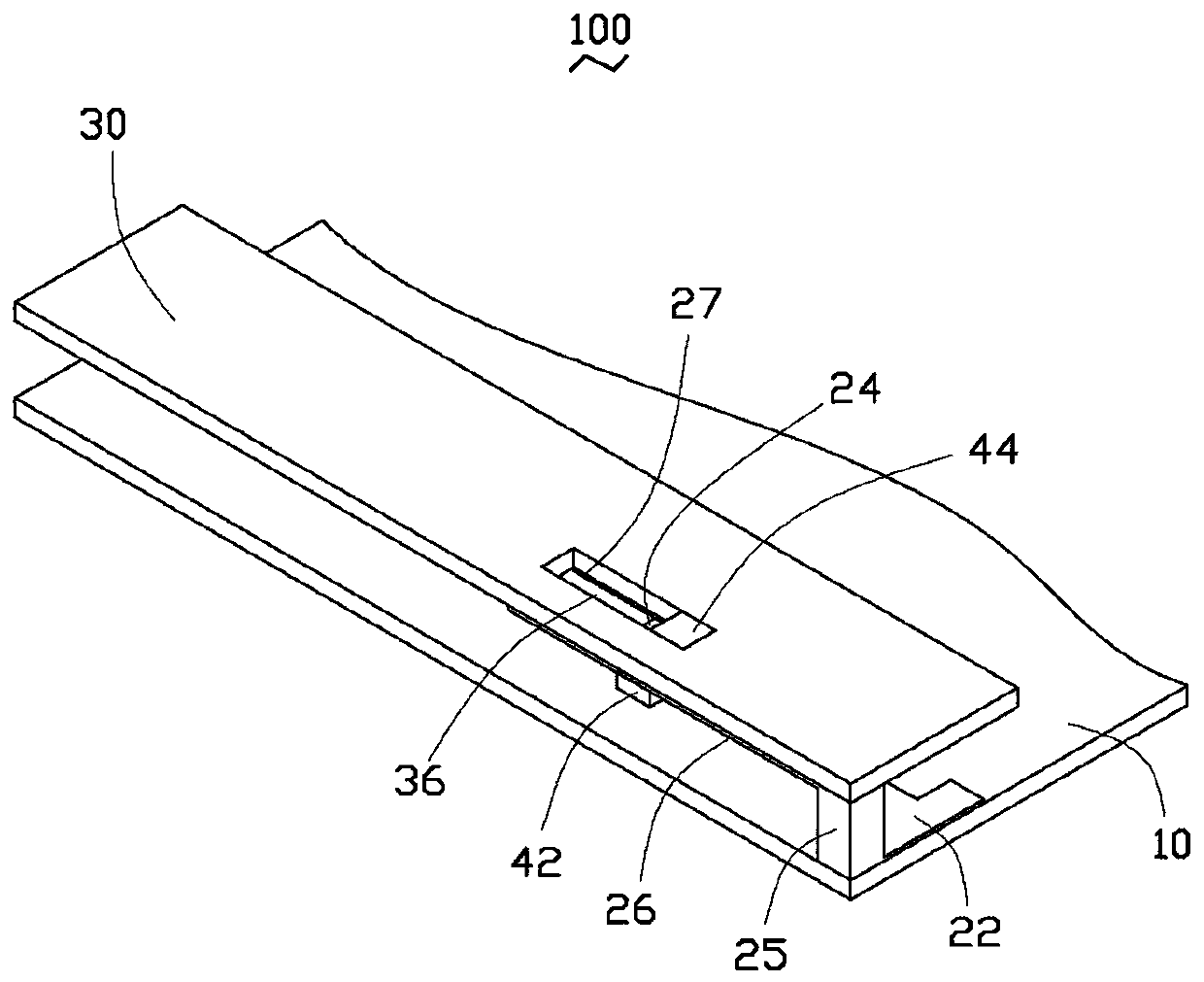
[0013] see figure 1 , a preferred embodiment of the present invention provides a wireless communication device 100, which can be a mobile phone or a personal digital assistant (Personal Digital Assistant, PDA).

[0014] In this embodiment, the wireless communication device 100 includes a carrier 10 , an antenna 20 , a housing 30 and an adjusting member 40 .

[0015] The carrier 10 can be a circuit board of a wireless communication device 100, on which a feed point 12 and a ground point 14 are arranged, the feed point 12 is used to feed current to the antenna 20, and the ground point 14 is used to provide a Provide grounding.

[0016] The antenna 20 is set on the carrier 10 and can be configured in any shape to send and receive wireless signals with any frequency, such as sending and receiving wireless fidelity (wireless fidelity, WIFI) signals, or sending and receiving global positioning system (Global Position System, GPS )Signal.

[0017] In this embodiment, the antenna 2...


PUM


Abstract

The present invention provides a wireless communication device, which includes a carrier, an antenna, a housing and an adjustment member. The antenna is arranged on the carrier. The housing covers the carrier and the antenna. The antenna includes a first radiation part and a The second radiating part is arranged at intervals. The adjusting part is made of conductive material, which is slidably arranged on the casing and connected between the first radiating part and the second radiating part. When the adjusting part slides relative to the casing , the relative positions of the adjusting member and the first radiating part and the second radiating part are changed to adjust the resonant frequency of the antenna. The wireless communication device can fine-tune the resonant frequency of the antenna, thereby enhancing the versatility of the antenna.

Description

technical field [0001] The present invention relates to a wireless communication device, in particular to a wireless communication device capable of finely adjusting the frequency of sending and receiving of an antenna. Background technique [0002] In order to shorten the antenna design cycle of wireless communication devices such as mobile phones, most antennas are currently designed for specific wireless communication devices, that is, the size and spatial placement of the antenna only consider the installation environment inside the corresponding wireless communication device. However, when the installation position of the antenna needs to be changed, or the antenna needs to be applied to other wireless communication devices, the environment around the antenna changes, which will inevitably lead to a shift in its resonant frequency, which will affect the performance of transmitting and receiving signals. Contents of the invention [0003] In view of this, it is necessa...

Claims


Application Information

Patent Timeline
Patent Type & Authority Patents(China)
IPC IPC(8): H01Q5/10H01Q1/22H01Q1/36
Inventor 刘己圣
Owner SHENZHEN FUTAIHONG PRECISION IND CO LTD
Learn More