Coil winding machine of moving-coil motor

A hollow cup and winding machine technology, which is applied in the manufacture of motor generators, electrical components, electromechanical devices, etc., can solve the problems of low production efficiency, prolonging the production cycle of hollow cup coils, and inability to realize automatic operation of the coil immersion tin process, etc. Achieve the effect of shortening production cycle and improving production efficiency

Active Publication Date: 2014-03-26
SHENZHEN SHUANGHUAN QX MOTOR
View PDF3 Cites 10 Cited by
  • Summary
  • Abstract
  • Description
  • Claims
  • Application Information

AI Technical Summary

Problems solved by technology

[0004] The coreless motor coil winding machine provided by the present invention aims to solve the problems that the existing coreless motor coil winding machine cannot realize the automatic operation of the coil dipping tin process, prolong the production cycle of the coreless coil, and the production efficiency is low

Method used


Image

  • Coil winding machine of moving-coil motor
  • Coil winding machine of moving-coil motor
  • Coil winding machine of moving-coil motor

Examples


Embodiment Construction

[0033] In order to make the object, technical solution and advantages of the present invention clearer, the present invention will be further described in detail below in conjunction with the accompanying drawings and embodiments. It should be understood that the specific embodiments described here are only used to explain the present invention, not to limit the present invention.

[0034] The present invention will be described in detail below in conjunction with specific embodiments.

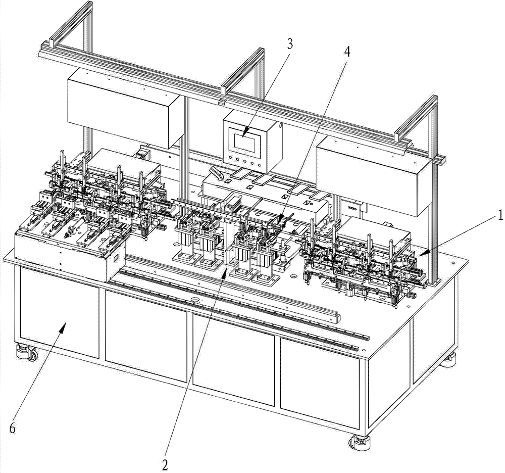
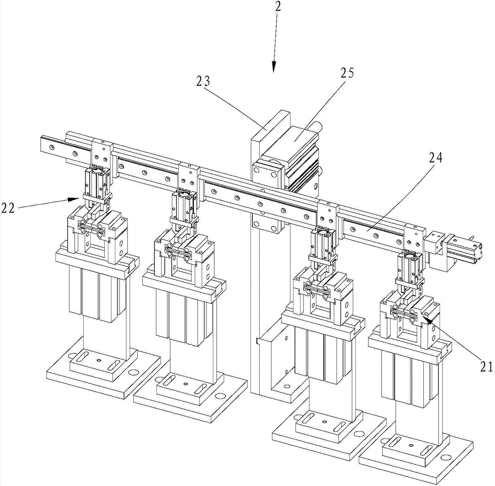
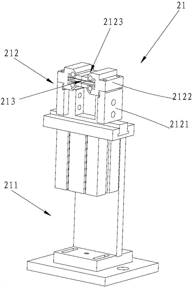
[0035] Such as figure 1 and Figure 6 As shown, the embodiment of the present invention provides a coreless motor coil winding machine, which includes a winding mechanism 1, a thread removal mechanism 2 and a control mechanism 3, and the control mechanism 3 controls the operation of the winding mechanism 1 and the thread removal mechanism 2. The wire mechanism 1 winds the coil, winds the enameled wire into a coil with two wire ends and multiple electrode ends, the wire end removal mechanism ...


PUM


Abstract

The invention belongs to the technical field of a motor coil winding machine and particularly relates to a coil winding machine of a moving-coil motor. The coil winding machine comprises a winding mechanism capable of winding a varnished wire into a coil with two thread residues and a plurality of electrode tips, a thread residue removing mechanism for clamping a coil and removing the thread residues and a control mechanism arranged on a rack, wherein the control mechanism is used for controlling the movement of the winding mechanism and the thread residue removing mechanism; the coil winding machine comprises a dip soldering furnace and a dip soldering mechanism for clamping the coil arranged in the thread residue removing mechanism and carrying out a dip soldering process on the electrode tips; the dip soldering mechanism comprises a clamping part for clamping the coil, an overturning part for overturning the coil and a moving part for driving the clamp part to move and dipping the overturned electrode tips into the dip soldering furnace; the moving part is connected with the clamping part and the clamping part is mounted on the moving part; the control mechanism is used for controlling the movement of the clamping part, the overturning part and the moving part; the clamping part is used for automatically clamping the coil; the overturning part is used for overturning the coil; the moving part is used for placing the electrode tips into the dip soldering furnace to finish the dip soldering operation.

Description

technical field [0001] The invention belongs to the technical field of motor coil winding machines, in particular to a hollow cup motor coil winding machine. Background technique [0002] The hollow cup motor is a DC, permanent magnet, and servo micro motor. It adopts a hollow cup rotor, which completely eliminates the power loss caused by the eddy current formed by the iron core. At the same time, its weight and moment of inertia are greatly reduced, thereby reducing the mechanical energy of the rotor itself. It has outstanding energy-saving characteristics, sensitive and convenient control characteristics and stable operation characteristics. At the same time, the energy density of the coreless motor is greatly improved. Compared with the iron core motor of the same power, its weight and volume are greatly reduced. As A high-efficiency energy conversion mechanism, the coreless motor represents one of the development directions of the motor. [0003] The coreless motor coi...

Claims


Application Information

Patent Timeline
Patent Type & Authority Applications(China)
IPC IPC(8): H02K15/04
Inventor 黄剑兴范圣秉刘晋权
Owner SHENZHEN SHUANGHUAN QX MOTOR
Why Eureka
Try Eureka