Electronic equipment and hinge for electronic equipment

A technology for electronic equipment and hinges, applied in the field of hinges, can solve problems such as affecting appearance and performance, and achieve the effect of meeting design requirements, meeting the requirements of thinness, and smooth appearance.

Active Publication Date: 2014-03-26
LENOVO (BEIJING) CO LTD
View PDF4 Cites 5 Cited by
  • Summary
  • Abstract
  • Description
  • Claims
  • Application Information

AI Technical Summary

Problems solved by technology

However, limited by the thinner screen and the existing structural hinges, a large gap will be formed between the u

Method used


Image

  • Electronic equipment and hinge for electronic equipment
  • Electronic equipment and hinge for electronic equipment
  • Electronic equipment and hinge for electronic equipment

Examples


Embodiment 1

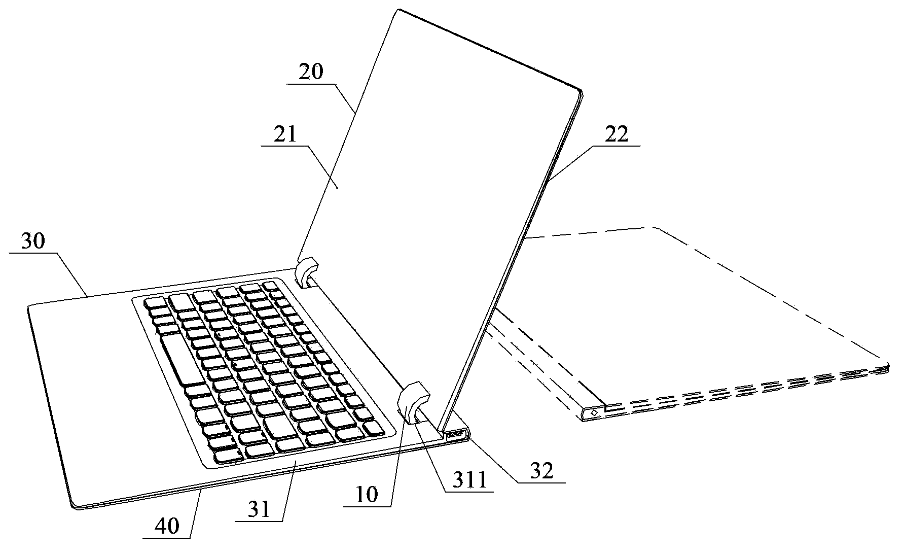
[0048] See figure 1 , which is a schematic diagram of the overall structure of the notebook computer described in this embodiment. In order to clearly and briefly show the open state and the closed state of the notebook computer, the notebook computer in the open state is mainly shown in solid lines in the figure, and the notebook computer in the closed state is shown in dotted lines.

[0049] The same as the main body of a traditional notebook computer, the notebook computer realizes the hinge of the first body 20 and the second body 30 through a connecting piece; in this embodiment, the connecting piece is a hinge 10, so that the first body 20 and the second body The relative positional state of 30 is switched between an open state and a closed state. Wherein, the first surface shell 31 of the second body 30 has a groove 311, and is configured as: the second surface shell 21 of the first body 20 in the closed state and the first surface shell of the second body 30 31 are i...

Embodiment 2

[0068] See Figure 12 , which is a schematic diagram of the overall structure of the notebook computer described in the second embodiment.

[0069] This solution is the same as the first embodiment in that the connection between the first body 20' and the second body 30' is realized through the connecting piece 10'; similarly, the first surface shell 31' of the second body 30' has a groove 311', and configured so that: the second surface shell 21' of the first body 20' in the closed state is in contact with the first surface shell 31' of the second body 30', and the connector 10 in this state ' is accommodated in the groove 311', so that the connector 10' is hidden inside the electronic device.

[0070] Specifically, one end of the connector 10' is hinged to the connection end of the second body 30', and the groove 311' extends from the connection end to the middle of the first surface shell 31' of the second body 30'; the connector The other end of 10' is hinged to the midd...


PUM


Abstract

The invention discloses electronic equipment which comprises a first body, a second body and a connecting piece, wherein a groove is formed in a first surface casing of the second body; the connecting piece is connected with the first body and the second body so that the first body and the second body are enabled to be switched between an opening state and a closed state in a relative position state, and are configured in a manner that a second surface casing of the first body in the closed state is contacted with the first surface casing of the second body, and the connecting piece is accommodated inside the groove, so that the connecting piece can be hidden inside the electronic equipment and the connecting piece cannot be perceived by a user in any angle. On such basis, the invention further provides a hinge applied to the electronic equipment. The structural improvement ensures that no externally exposed interface is formed in the outer sides of the two bodies.

Description

technical field [0001] The invention relates to the field of electronic technology, in particular to an electronic device and a hinge used for the electronic device. Background technique [0002] With the development of science and technology and the gradual improvement of user needs, the optimized design of different types of electronic products is constantly being introduced. On the one hand, reducing the exposed interface of electronic equipment in the non-use state has become a mainstream design trend, so as to prevent dust and particles from falling into the exposed interface and affect its normal use, and at the same time improve the appearance of electronic products. [0003] For example, a signal port, a power port, or an exposed interface formed by a hinge connection structure; in particular, the exposed interface at the hinge connection position is formed based on the limitations of the existing hinge structure, and there is no need for external functions in any us...

Claims


Application Information

Patent Timeline
IPC IPC(8): H05K5/02F16C11/12
CPCG06F1/1616G06F1/162G06F1/1679G06F1/1681H05K5/0226
Inventor 梁润生
Owner LENOVO (BEIJING) CO LTD
Why Eureka
Try Eureka