A method for tightening an electromechanical brake, and an electromechanical brake

A brake, electromechanical technology, applied in the direction of brake components, brakes, brake types, etc., can solve problems such as poor characteristics

Inactive Publication Date: 2014-03-26
CONTINENTAL TEVES AG & CO OHG
View PDF4 Cites 7 Cited by
  • Summary
  • Abstract
  • Description
  • Claims
  • Application Information

AI Technical Summary

Problems solved by technology

Structurally, a reduction in the force drop during cooling can be achieved by the lower stiffness of the brake caliper, but this can lead to perceptibly poorer behavior when the service brake is actuated

Method used


Image

  • A method for tightening an electromechanical brake, and an electromechanical brake
  • A method for tightening an electromechanical brake, and an electromechanical brake

Examples


Embodiment Construction

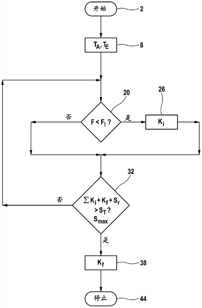
[0032] figure 1 A flow diagram of a preferred embodiment of the method according to the invention is shown in . At start 2, the vehicle is stopped and the parking brake function is activated. In box 8, with the help of the loss of clamping force within the first minute after start 2 and the starting temperature T of the brake disc A and predictable final temperature T E or difference T A -T E to determine the expected total clamping force loss S of the brake T .

[0033] Total clamping force loss S T The calculation of can also be carried out not only at the beginning of the method as shown here but between further method steps, so that the initially obtained values ​​can be corrected to a certain extent if necessary.

[0034] In decision 20 it is checked whether the momentarily present force or the clamping force F is less than the minimum specified value F of the clamping force l (l stands for Limit). If this is the case, the method branches to box 26, where a force...


PUM


Abstract

The invention relates to a method for tightening an electromechanical brake having an actuator which is driven by an electric motor and which presses a brake element against a brake body with a force stroke in order to implement a parking brake functionality, wherein for the purpose of tightening a number of chronologically successive force strokes are carried out, the intention being to configure the tightening process as effectively and reliably as possible. For this purpose, the force strokes are each applied as soon as the tensioning force of the brake drops below a predefined tensioning force minimum setpoint value, wherein the respective force stroke is applied in such a way that a predefined maximum tensioning force is not exceeded, wherein the expected total loss of tensioning force is determined on the basis of the initial temperature of the brake body and the expected final temperature of the brake body, and wherein the time of a last force stroke is selected in such a way that at this time the sum of the previous force strokes, the last force stroke and the still expected loss of tensioning force exceeds the expected total loss of tensioning force.

Description

technical field [0001] The invention relates to a method for supplementary clamping (Nachspannen) of an electromechanical brake with an actuator driven by an electric motor, which is operated with a force increase (Krafthub) for the parking brake function. The brake element is pressed against the brake body, wherein a plurality of successive force increases are carried out in order to supplement the clamping. Furthermore, the invention relates to a corresponding electromechanical brake. Background technique [0002] In electromechanical brakes (EMB), or electromechanically actuated brakes, the respective wheels are braked purely electrically by means of electrically operated actuators. Usually, such brakes are designed as disk brakes, wherein during the braking process, an electric motor via a spindle drive driven by it presses a brake piston against a brake disk. Such brakes are usually controlled by a control and regulating unit and usually each include their own electro...

Claims


Application Information

Patent Timeline
Patent Type & Authority Applications(China)
IPC IPC(8): B60T13/74B60T7/12F16D66/00
CPCF16D2066/006B60T13/74F16D65/38B60T17/221B60T8/17F16D2066/001B60T7/12B60T7/108F16D66/00F16D2065/386B60T2270/86
Inventor W·理查特C·布埃尔特
Owner CONTINENTAL TEVES AG & CO OHG
Why Eureka
Try Eureka