Automatic upper glue spraying component and automatic upper glue spraying machine

A technology of automatic glue spraying machine and driving components, which is applied in the fields of automatic glue spraying components for shoe uppers, automatic glue spraying machines for shoe uppers, and glue spraying devices. It can solve problems such as low efficiency, glue diffusion, and low glue spraying efficiency, and reduce glue flow. Diffusion, improve product quality, avoid the effect of glue sticking

Inactive Publication Date: 2014-04-02
曹县雅天工艺品有限公司
View PDF6 Cites 16 Cited by
  • Summary
  • Abstract
  • Description
  • Claims
  • Application Information

AI Technical Summary

Problems solved by technology

Although this glue spraying machine can spray glue on the outsole of shoes, there are some problems: 1. There is only one glue spray head, that is, only one shoe can be sprayed glue at the same time, so there is a problem of low efficiency
2. After the glue is sprayed, it is in the form of mist, and the air flow makes the atomized glue easy to diffuse, which in turn affects the quality of the upper and the environment of the workshop
3. This glue spraying machine needs to scan first and then spray glue, so there is a problem of low glue spray efficiency
4. The outsole of the shoe is a curved surface. Obviously, the orientation of the spray head of this glue spraying machine relative to the horizontal plane cannot be adjusted. Obviously, it is impossible to guarantee that the orientation of the spray head and any position of the shoe outsole is always the same. In other words, there is uneven glue spraying quality , particularly blurred edge lines in areas covered by glue

Method used


Image

  • Automatic upper glue spraying component and automatic upper glue spraying machine
  • Automatic upper glue spraying component and automatic upper glue spraying machine
  • Automatic upper glue spraying component and automatic upper glue spraying machine

Examples


Embodiment Construction

[0029] The following are specific embodiments of the present invention and in conjunction with the accompanying drawings, the technical solutions of the present invention are further described, but the present invention is not limited to these embodiments.

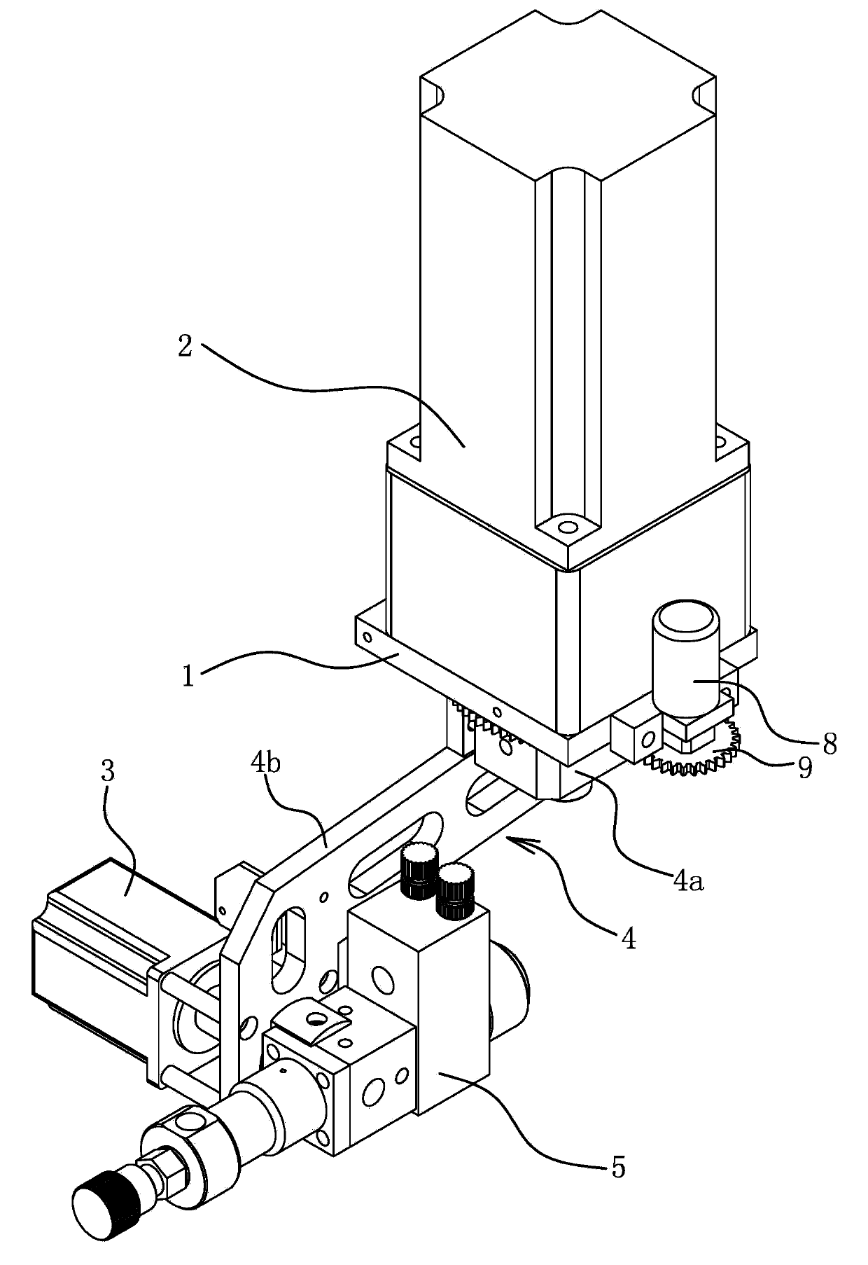
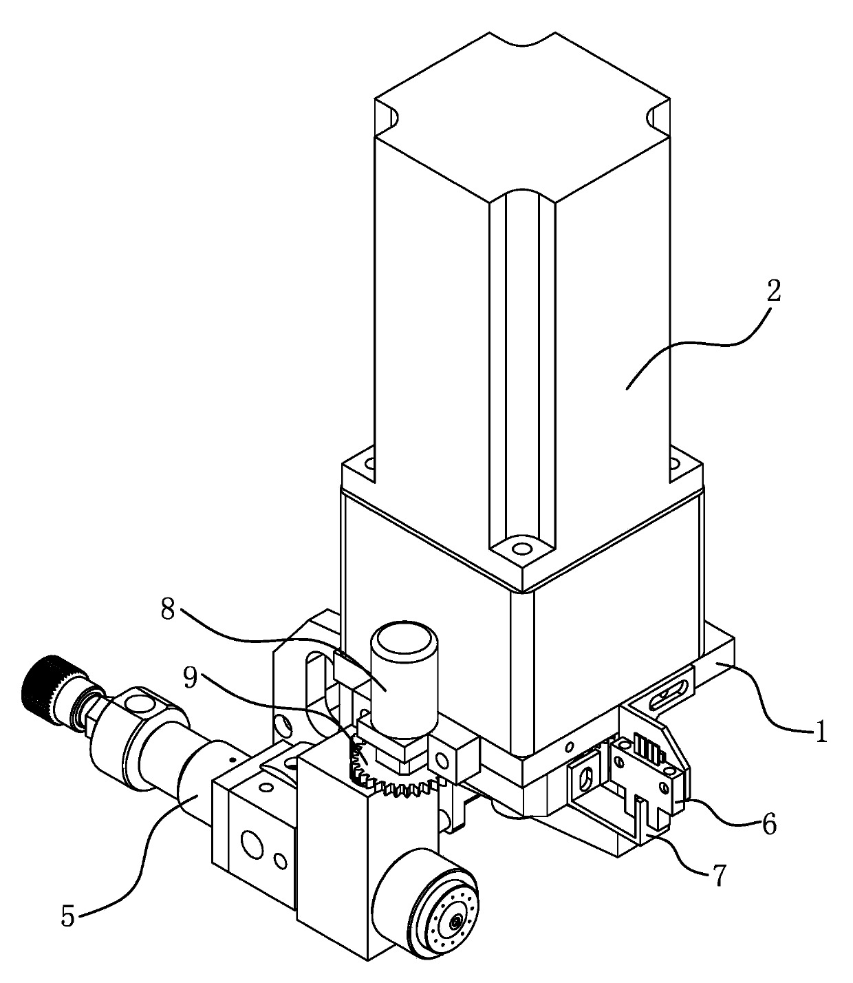
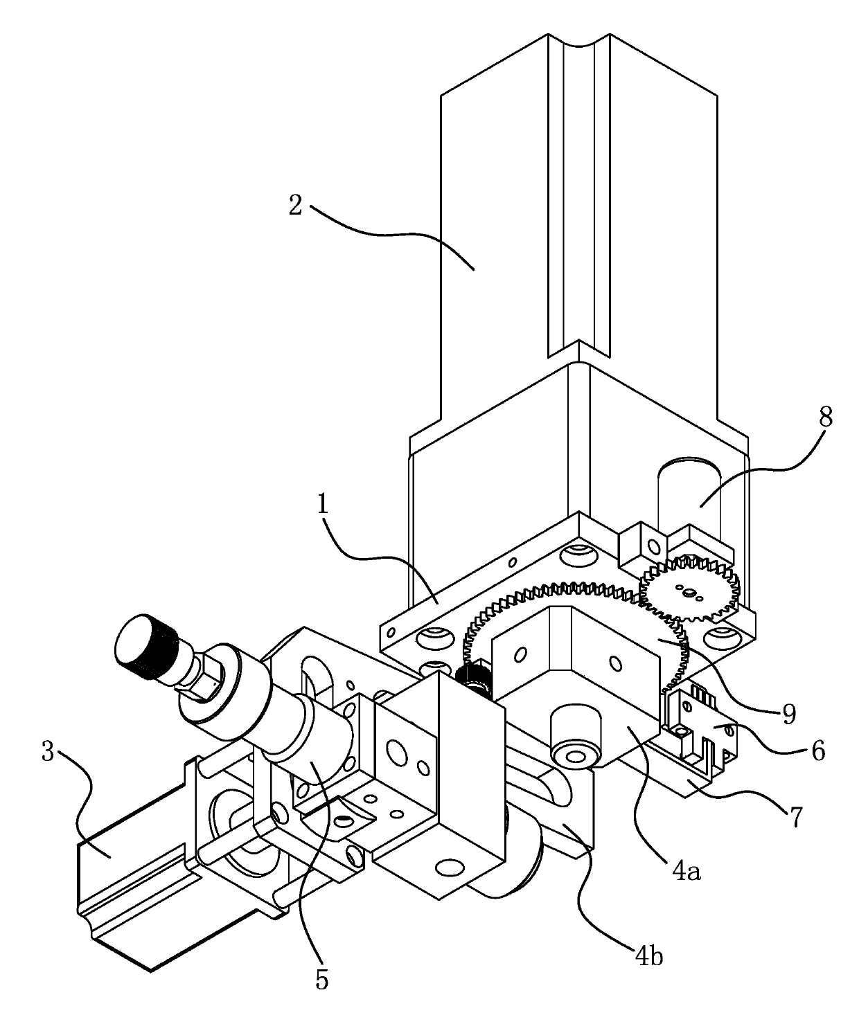
[0030] Such as Figures 1 to 4 As shown, the shoe upper automatic glue spray assembly A includes a base plate 1 , a first motor 2 , a second motor 3 , a connecting piece 4 and a glue gun 5 .

[0031] The base plate 1 is a basic component, that is, for the installation of the first motor 2 and other components, and is also a connecting component for the shoe upper automatic glue spraying assembly A to be connected with other devices.

[0032]The shell of the first motor 2 is fixedly connected with the base plate 1 . The rotating shaft of the first motor 2 is fixedly connected to the housing of the second motor 3 through a connecting piece 4; specifically, the second motor 3 is located on one side of the first motor 2. Pre...


PUM


Abstract

The invention provides an automatic upper glue spraying component and an automatic upper glue spraying machine, belongs to the technical field of operation, and solves the problem that spraying nozzles of existing glue spraying machines cannot be kept in the same direction with any positions of shoe outsoles. The automatic upper glue spraying component comprises a first motor, a glue spraying gun, a second motor and a connecting piece. A rotating shaft of the first motor and a shell of the second motor are fixedly connected through the connecting piece. The glue spraying gun is fixedly connected with a rotating shaft of the second motor. The direction of the axis of the rotating shaft of the first motor is different from that of the axis of the rotating shaft of the second motor. According to the automatic upper glue spraying component, the direction of a nozzle of the glue spraying gun and the distance between the glue spraying gun and the rotating shaft of the first motor can be adjusted, and can be automatically adjusted according to program settings during glue spraying, so that the glue spraying gun can be ensured to face to-be-sprayed points in the optimal direction, and intervals between the nozzle of the glue spraying gun and to-be-sprayed surfaces are ensured to be uniform. The automatic upper glue spraying component used for spraying glue to uppers has the advantage of improving product quality.

Description

technical field [0001] The invention belongs to the technical field of operations, and relates to a glue spraying device, in particular to an automatic glue spraying assembly for shoe uppers. [0002] The invention belongs to the technical field of operations, and relates to a glue spraying device, in particular to an automatic glue spraying machine for shoe uppers. Background technique [0003] Traditional shoemaking is all made by hand; due to the various processes of shoemaking, more manpower is required. With the development of society, the cost of labor is getting higher and higher, and the shortage of workers is becoming more and more; this will lead to the abnormal production of factories, and the increase of the cost of shoes and the decrease of market competitiveness. [0004] For example, in the gluing process, manual gluing is not only inefficient, the accuracy cannot be guaranteed, but also the operation is complicated, the production product is single, and the ...

Claims


Application Information

Patent Timeline
Patent Type & Authority Applications(China)
IPC IPC(8): A43D25/18
Inventor 陈兵徐雅红
Owner 曹县雅天工艺品有限公司
Why Eureka
Try Eureka