Axis-controlled positioning occipital jaw with displacement positioning suspension

A positioning type, occiput-maxillary belt technology, applied in the field of medical equipment, can solve problems affecting the effect of treatment, occipital-maxillary belt deviation, difficulties, etc., to achieve the effect of reducing the fixed-point span, avoiding the movement of the rollers, and improving the stability

Inactive Publication Date: 2015-10-14
NINGBO YINZHOU YUNFAN ENG CONSULTING
View PDF4 Cites 0 Cited by
  • Summary
  • Abstract
  • Description
  • Claims
  • Application Information

AI Technical Summary

Problems solved by technology

[0003] 1. Unable to achieve precise positioning
There must be a large interval between the grooves of the crossbar, so that the partition between adjacent grooves has a certain strength to withstand the lateral pressure generated by the hanging ring, and this interval makes the hanging ring in the horizontal direction. The length of the horizontal displacement on the bar must be an integral multiple of the interval, which makes the horizontal position of the occiput-maxillary belt impossible to accurately locate
[0004] 2. It is impossible to adjust the horizontal position of the occiput and jaw strap conveniently
This is very inconvenient when the patient's head is already in the occipital-maxillary strap, and it is even more difficult if the patient is asked to adjust to their own comfort because it requires the patient to reach over the top of the head to see the eyes. Operate from an invisible location
[0005] 3. Poor stability of the occipital and maxillary belt after positioning
Since the occiput-chin strap is positioned by the hanging ring on its top, and the hanging ring is in the groove of the cross bar, although the upper beam of the hanging ring cannot move along the longitudinal direction of the cross bar, it can move along the transverse direction of the cross bar. The lateral movement of the hanging ring will cause the deviation of the occipital and maxillary belt, which will cause discomfort to the patient and affect the effect of the treatment

Method used


Image

  • Axis-controlled positioning occipital jaw with displacement positioning suspension
  • Axis-controlled positioning occipital jaw with displacement positioning suspension
  • Axis-controlled positioning occipital jaw with displacement positioning suspension

Examples


Embodiment Construction

[0030] The present invention will be further described below in conjunction with the accompanying drawings and embodiments.

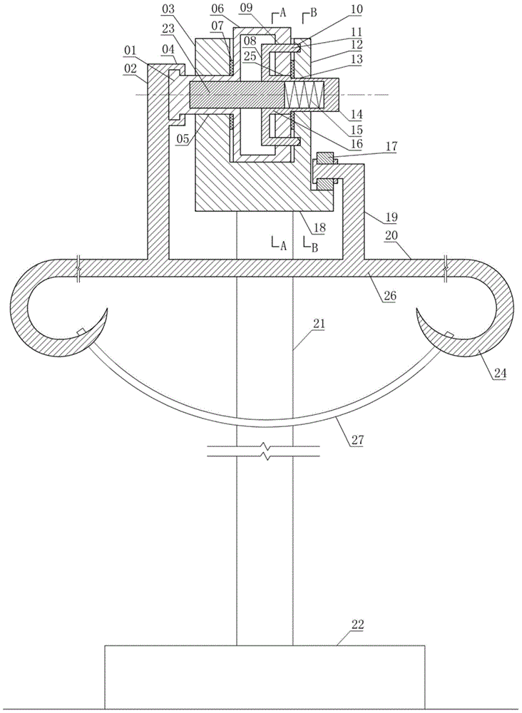
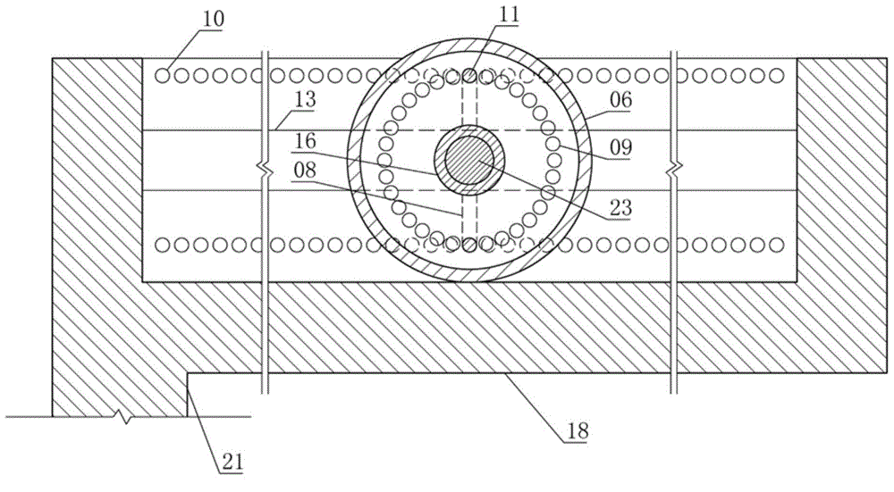
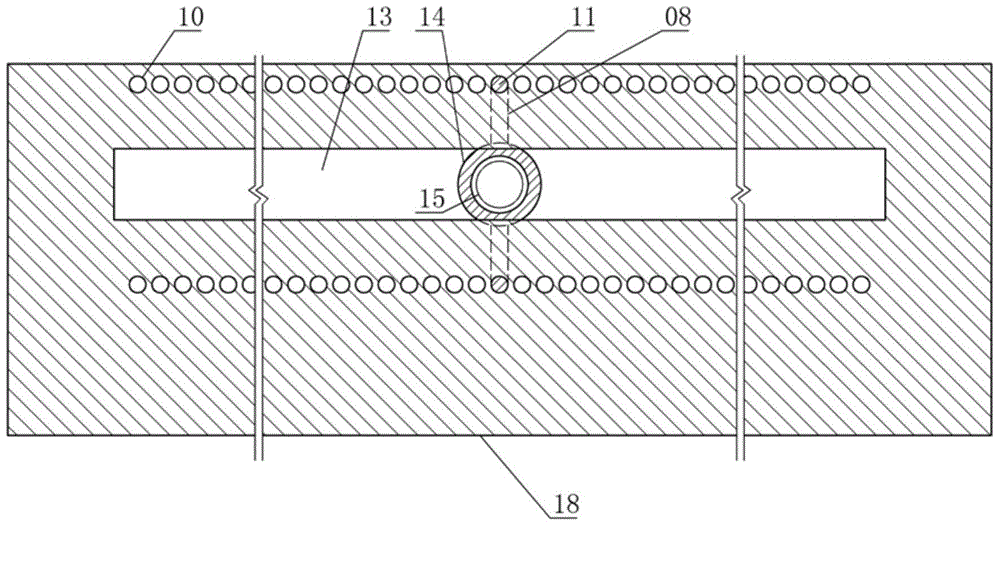
[0031] Shaft control positioning type pillow jaw belt displacement positioning type suspension, consisting of main shaft 01, left shaft frame 02, shaft end sliding sleeve 04, roller 06, washer 07, pin hole 09, spring 15, balance wheel 17, right shaft frame 19 , Bottom suspension 20, column 21, base 22, stem 23, hook 24, through hole 25, crossbeam 26, occipital jaw band 27, strip chute and fork-shaped sliding pin constitute.

[0032] The bar-shaped chute is a bar-shaped structure with a U-shaped cross section, closed ends and an open top. The strip chute is made of left wheel block 03, shaft crossing groove 05, right wheel block 12, base plate 18, right groove 13 and positioning hole 10. Wherein the left wheel chock 03 and the right wheel chock 12 are vertical rectangular plates, the left wheel chock 03 and the right wheel chock 12 are parallel to each ...


PUM


Abstract

The invention relates to the technical field of medical instruments, in particular to a displacement positioning type suspension of an shaft-control positioning type occipital jaw belt. The displacement positioning type suspension is composed of a spindle, a left shaft frame, a shaft-end sliding sleeve, a gasket, a pin passing hole, a spring, a balancing wheel, a right shaft frame, a bottom suspension, an upright, a base, a core column, a hook, a through hole, a cross beam, the occipital jaw belt, a bar-shaped sliding groove and a fork-shaped sliding pin, the bar-shaped sliding groove is of a bar-shaped structure with the cross section to be U-shaped, two ends closed and the top open, a roller is a cylindrical shell and is arranged in the bar-shaped sliding groove, and a cylindrical spindle integrally formed with the roller and concentric with the roller is arranged on the left end face of the roller. By the displacement positioning type suspension, a patient can autonomously and accurately position the occipital jaw belt, and the occipital jaw belt can be prevented from displacement, thereby having better stability.

Description

technical field [0001] The invention relates to the technical field of medical devices, in particular to an axis-controlled positioning type occipital-mandibular band displacement positioning type suspension. Background technique [0002] The application number is 200820187247.9 "cervical vertebra traction frame" comprises parts such as cross bar, groove, occiput and jaw strap and hanging ring, puts into the groove of cross bar to realize the positioning of occiput and jaw strap through the hanging ring of occiput and jaw strap. There are following defects in such technical features: [0003] 1. Precise positioning cannot be achieved. There must be a large interval between the grooves of the crossbar, so that the partition between adjacent grooves has a certain strength to withstand the lateral pressure generated by the hanging ring, and this interval makes the hanging ring in the horizontal direction. The horizontal displacement length on the bar must be an integral multi...

Claims


Application Information

Patent Timeline
Patent Type & Authority Patents(China)
IPC IPC(8): A61F5/045
Inventor 何文仙
Owner NINGBO YINZHOU YUNFAN ENG CONSULTING
Why Eureka
Try Eureka