Hot upsetting die seat of press

A press and hot upsetting technology, which is applied in the field of press hot upsetting mold bases, can solve problems such as safety accidents, easy to stab people, and jumping blocks to hurt people and other problems

Active Publication Date: 2014-04-02
AVIC STANDARD PARTS MFG
View PDF4 Cites 1 Cited by
  • Summary
  • Abstract
  • Description
  • Claims
  • Application Information

AI Technical Summary

Problems solved by technology

[0002] At present, the deformation of the head of the fastener is generally divided into upper mold molding and lower mold molding according to the shape of the head and processing requirements. Different molding methods require different mold holders. If the molding method changes, the corresponding mold holders need to be replaced. , especially in the standard parts industry, the processed products are often changed and the mold base is often changed. Frequent replacement is not only a waste of time, but it is difficult to find the center of the upper and lower mold bases, which affects the concentricity of the product head and the rod. It is also very unsafe. The base weighs nearly 100 catties, and it is easy to hurt people when moving it up and down. Also, when adjusting the concentricity of the upper and lower mold bases, if the control is not good, the upper and lower mold bases will collide, and it is easy to cause the jumping pieces to fly out and hurt people. cause safety accident

Method used


Image

  • Hot upsetting die seat of press
  • Hot upsetting die seat of press
  • Hot upsetting die seat of press

Examples


Embodiment 1

[0025] Embodiment 1: upper mold forming press hot heading die base

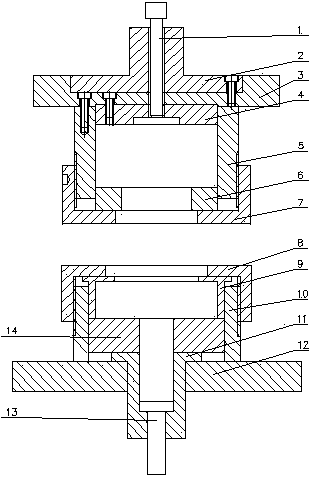
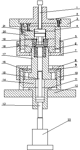
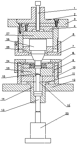
[0026] see Figure 1 to Figure 7 , the press hot heading die base of the present invention includes a punching rod 1, an upper template 3, an upper fixing seat 5, an upper back cap 7, a lower back cap 8, a lower fixing seat 10, a mandrel cover 11, and a lower template 12 , ejector rod 13, mold handle 2, backing plate A4, and upper fixing seat 5 are respectively fastened on the upper template 3, and the lower fixing seat 10 is fixed on the lower template 12, wherein: the punching rod 1 is installed in the mold handle 2, The guide sleeve 6 is placed inside the upper fixing seat 5, the upper back cap 7 is threadedly connected with the upper fixing seat 5, the ejector rod sleeve 11 is installed in the lower template 12, the ejector rod 13 is placed in the ejector rod sleeve 11, and the lower cushion sleeve 14 Be contained in push rod cover 11 upper sides, fixed cover 9 is placed in lower fixed seat 10, lower b...

Embodiment 2

[0027] Embodiment 2: Lower mold forming press hot heading die base

[0028] see Figure 1 to Figure 7 , the hot upsetting mold seat of the press, including the punching rod 1, the upper template 3, the upper fixing seat 5, the upper back cap 7, the lower back cap 8, the lower fixing seat 10, the ejector rod cover 11, the lower template 12, the top Material rod 13, mold handle 2, backing plate A4, and upper fixing seat 5 are respectively fastened on the upper template 3, and the lower fixing seat 10 is fixed on the lower template 12, wherein: the punching rod 1 is installed in the mold handle 2, and the guide sleeve 6 is placed inside the upper fixing seat 5, the upper back cap 7 is threadedly connected with the upper fixing seat 5, the ejector rod sleeve 11 is installed in the lower template 12, the ejector rod 13 is placed in the ejector rod sleeve 11, and the lower cushion sleeve 14 is installed in the On the upper side of the push rod cover 11, the fixed sleeve 9 is plac...


PUM


Abstract

The invention relates to a hot upsetting die seat of a press. The hot upsetting die seat comprises a knock-out rod (1), an upper die plate (3), an upper fixed seat (5), an upper safety nut (7), a lower safety nut (8), a lower fixed seat (10), an ejector sleeve (11), a lower die plate (12), a die handle (2) and a cushion plate A (4), wherein the upper fixed seat (5) is fixedly fastened on the upper die plate (3), and the lower fixed seat (10) is fixed on the lower die plate (12). The hot upsetting die seat is characterized in that the knock-out rod (1) is arranged in the die handle (2), a guide sleeve (6) is arranged in the upper fixed seat (5), and the upper safety nut (7) is in threaded connection with the upper fixed seat (5); the ejector sleeve (11) is arranged in the lower die plate (12), and an ejector rod (13) is arranged in the ejector sleeve (11); a lower cushion sleeve (14) is arranged on the upper side of the ejector sleeve (11), and a fixing sleeve (9) is arranged in the lower fixed seat (10); a die is arranged in each of the upper fixed seat (5) and the lower fixed seat (10). The hot upsetting die seat has high accuracy, and is simple, convenient, safe and practical.

Description

technical field [0001] The invention belongs to the technical field of die base components, and in particular relates to a hot heading die base for a press. Background technique [0002] At present, the deformation of the head of the fastener is generally divided into upper mold molding and lower mold molding according to the shape of the head and processing requirements. Different molding methods require different mold holders. If the molding method changes, the corresponding mold holders need to be replaced. , especially in the standard parts industry, the processed products are often changed and the mold base is often changed. Frequent replacement is not only a waste of time, but it is difficult to find the center of the upper and lower mold bases, which affects the concentricity of the product head and the rod. It is also very unsafe. The base weighs nearly 100 kg, and it is easy to hurt people when moving it up and down. Also, when adjusting the concentricity of the upp...

Claims


Application Information

Patent Timeline
Patent Type & Authority Applications(China)
IPC IPC(8): B21J13/03B21J13/02
Inventor 陈菊郑友
Owner AVIC STANDARD PARTS MFG
Why Eureka
Try Eureka