Reinforcement Welded Mesh Weft Line Positioning Device

A technology of steel welded mesh and positioning device, which is applied in the direction of auxiliary devices, welding equipment, welding equipment, etc., and can solve problems such as limited position, waste products, and uneven weft outcropping

Active Publication Date: 2016-08-17
ANHUI BRC & MA STEEL WELDMESH +1
View PDF6 Cites 0 Cited by
  • Summary
  • Abstract
  • Description
  • Claims
  • Application Information

AI Technical Summary

Problems solved by technology

[0002] When the welded steel mesh is produced, the wefts in the weft warehouse fall one by one with the weft feeding mechanism. On the one hand, the wefts are in a free state in the weft warehouse, so that each weft has a misalignment in the length direction; on the other hand, Due to the structure, the position of the guide plate of the weft thread library is limited. After the weft thread falls away from the guide plate, it loses the left and right constraints and is in a free state. At this time, the influence of two factors will cause the weft thread to form a large gap in the length direction. Misalignment, the direct manifestation is that the weft of the finished welded mesh is uneven, which not only affects the appearance quality of the product, but also forms waste products if the deviation exceeds the standard
For some special requirements of weft "zero" outcropping welding mesh products, due to the existence of errors, the outcropping may exceed the standard or the solder joints on the farthest side cannot be welded, resulting in the failure of production of such products

Method used


Image

  • Reinforcement Welded Mesh Weft Line Positioning Device
  • Reinforcement Welded Mesh Weft Line Positioning Device
  • Reinforcement Welded Mesh Weft Line Positioning Device

Examples


Embodiment Construction

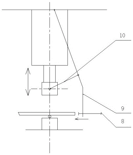
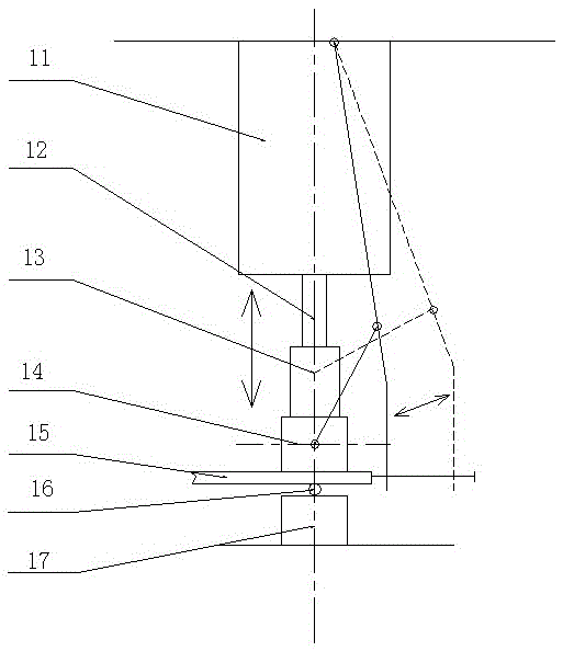
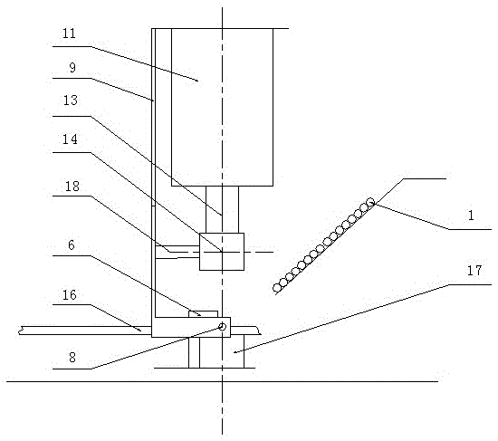
[0012] from figure 1 , figure 2 , image 3 It can be seen that the weft line positioning device for welded steel mesh of the present invention includes a fixed column 18, a connecting plate 10, a swing bar 9, and a push plate 8; , the other end of connecting plate 10 is hinged with fork 9, and the upper end of fork 9 is connected on the welded mesh main frame, and its lower end is connected with push plate 8. Wherein, the connecting plate 10, the swing rod 9, and the fixed column 18 form a link mechanism, and the adjustable push plate 8 is used to adjust the position of the weft thread 15 to be positioned. The position of the push plate 8 is adjustable, that is, the position of the push plate 8 can be adjusted horizontally relative to the fork 9.

[0013] Wherein, the front end of the fixed column 18 is fixedly connected behind the electrode block 14 at the rightmost end of the welding net host; the upper end of the swing rod 9 is hinged on the working cylinder 11 at the r...


PUM


Abstract

The invention discloses a weft wire locating device of a steel bar welding mesh. The weft wire locating device comprises a fixing post, a connecting plate, an oscillating rod and a pushing plate, wherein the front end of the fixing post is connected to a welding mesh main machine, the rear end of the fixing post is hinged to the connecting plate which is horizontally arranged, the other end of the connecting plate is hinged to the oscillating rod, the upper end of the oscillating rod is connected to the welding mesh main machine, and the lower end of the oscillating rod is connected with the pushing plate. When the weft wire locating device works, welding weft wires can be fixed by a magnetic limiting plate after the welding weft wires freely fall from a weft wire storeroom, an upper electrode block is driven to move downwards to prepare for welding by an air cylinder rod, the weft wire locating device does corresponding motion during a falling process, the pushing plate is enabled to move and push the weft wires to be in position, and the welding can be carried out when the weft wires reach to needed positions. According to the weft wire locating device disclosed by the invention, accurate falling position of the weft wires can be ensured, thus the weft wires are flush with each other when the steel bar welding mesh is in welding, and the attractive appearance of a product is ensured while the quality of the product is ensured.

Description

technical field [0001] The invention relates to a device for positioning the weft during the production of welded steel mesh, which belongs to the supporting device of the welded mesh host. Background technique [0002] When the welded steel mesh is produced, the wefts in the weft warehouse fall one by one with the weft feeding mechanism. On the one hand, the wefts are in a free state in the weft warehouse, so that each weft has a misalignment in the length direction; on the other hand, Due to the structure, the position of the guide plate of the weft thread library is limited. After the weft thread falls away from the guide plate, it loses the left and right constraints and is in a free state. At this time, the influence of two factors will cause the weft thread to form a large gap in the length direction. Misalignment, the direct manifestation is that the weft of the finished welded mesh is uneven, which not only affects the appearance quality of the product, but also form...

Claims


Application Information

Patent Timeline
Patent Type & Authority Patents(China)
IPC IPC(8): B23K11/36B23K37/04
CPCB23K11/36B23K37/04
Inventor 朱文生
Owner ANHUI BRC & MA STEEL WELDMESH
Why Eureka
Try Eureka