
Mechanical device for hardware machining

A technology of mechanical devices and hardware, applied in mechanical equipment, bearing components, conveyor objects, etc., can solve the problems of high error rate, high labor cost, low degree of automation, etc., to achieve high placement efficiency, reduce labor costs, structure Cleverly designed effects

Active Publication Date: 2021-03-30
HENAN POLYTECHNIC UNIV
View PDF24 Cites 0 Cited by
  • Summary
  • Abstract
  • Description
  • Claims
  • Application Information

AI Technical Summary

Problems solved by technology

[0003] Generally, when processing a group of bearings, it is first necessary to put the outer ring and the inner ring of the bearing together, and then set rolling steel balls between the outer ring and the inner ring, and then carry out subsequent processing. The disadvantage is that it is difficult to accurately place the rolling steel balls between the outer ring of the bearing and the inner ring of the bearing. The degree of automation is not high. Generally, it is filled manually, which has a high error rate and high labor costs.

Method used


Image

  • Mechanical device for hardware machining
  • Mechanical device for hardware machining
  • Mechanical device for hardware machining

Examples


Embodiment Construction

[0035] In order to make the purpose, technical solutions and advantages of the embodiments of the present disclosure clearer, the technical solutions of the embodiments of the present disclosure will be clearly and completely described below in conjunction with the accompanying drawings of the embodiments of the present disclosure. Apparently, the described embodiments are some of the embodiments of the present disclosure, not all of them. Based on the described embodiments of the present disclosure, all other embodiments obtained by persons of ordinary skill in the art without creative effort fall within the protection scope of the present disclosure.

[0036] Unless otherwise defined, the technical terms or scientific terms used in the present disclosure shall have the usual meanings understood by those skilled in the art to which the present disclosure belongs. The words "comprising" or "comprising" and similar words used in the present disclosure mean that the elements or ...


PUM


Abstract

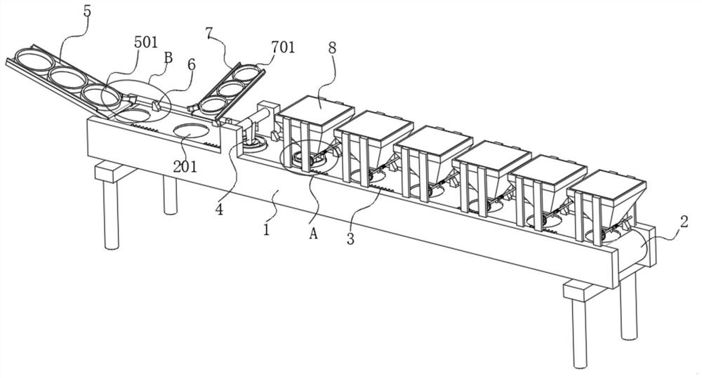
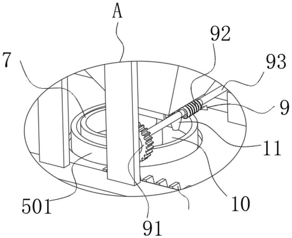
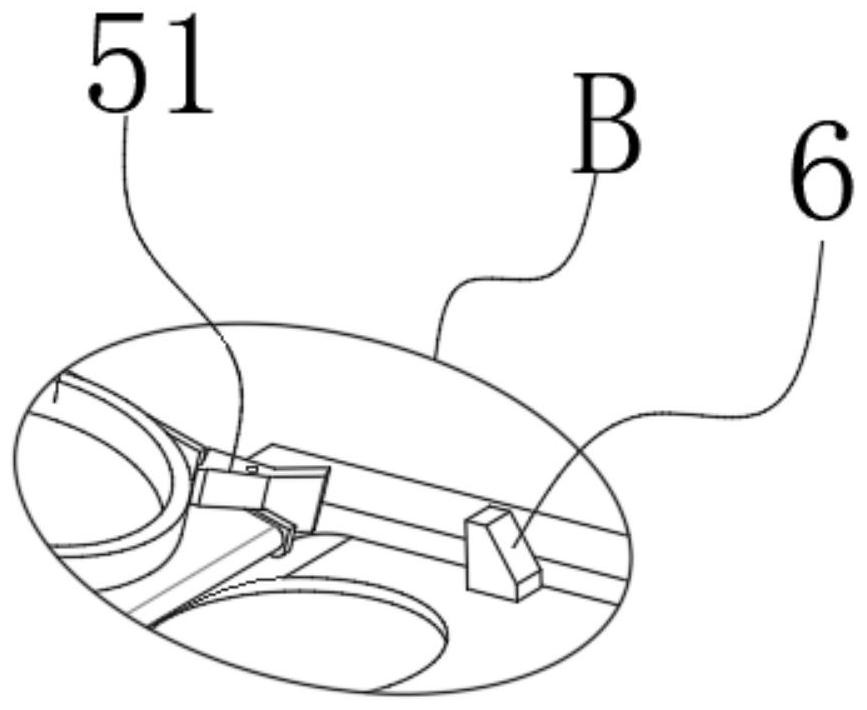
The invention discloses a mechanical device for hardware machining. The mechanical device comprises a conveying frame, a conveying belt is arranged on the conveying frame, a plurality of feeding boxesused for containing steel balls are arranged above the conveying belt, worm wheels are rotationally connected to openings in the bottoms of the feeding boxes, lower baffles are fixedly installed at the bottoms of the feeding boxes, the worm wheels are located in the baffles, the lower baffles fixedly communicate with discharging nozzles, discharging assemblies are arranged below the feeding boxes, and the discharging assemblies can drive the discharging nozzles to conduct intermittent discharging in the continuous conveying process of the conveying belt. According to the mechanical device forhardware machining, through the discharging assemblies, power conveyed by the conveying belt is converted into intermittent power of the discharging boxes, that is, the steel balls in the dischargingboxes can be stably conveyed into a containing groove according to conveying of the conveying belt, the containing efficiency is high, manual containing is not needed, and the labor cost is greatly reduced.

Description

technical field [0001] The invention relates to hardware processing technology, in particular to a mechanical device for hardware processing. Background technique [0002] Hardware refers to tools obtained by processing and casting gold, silver, copper, iron, tin and other metals, which are used to fix things, process things, decorate, etc. Bearings are one of the most common hardware parts. Bearings are contemporary An important component in mechanical equipment. Its main function is to support the mechanical rotating body, reduce the friction coefficient during its movement, and ensure its rotation accuracy. It is a metal processing part. The existing bearings generally include the outer ring of the bearing. , bearing inner ring and matching steel balls. [0003] Generally, when processing a group of bearings, it is first necessary to put the outer ring and the inner ring of the bearing together, and then set rolling steel balls between the outer ring and the inner ring, ...

Claims


Application Information

Patent Timeline
IPC IPC(8): F16C43/04F16C43/06B65G47/12B65G47/08
CPCF16C43/04F16C43/06B65G47/12B65G47/08
Inventor 王建平张晓辉陈旭刘金来张明军李瑜曲海军廖建国黄垂总张新民
Owner HENAN POLYTECHNIC UNIV
Learn More