Single-drive-point joint turnout

A joint turnout and driving point technology, which is applied in the direction of mechanical equipment for manipulating turnouts or line breakers, railway car body parts, railway signals, etc., can solve problems such as turnout system paralysis and lower system reliability, and achieve improved reliability. sexual effect

Active Publication Date: 2014-04-02
CHINA RAILWAY BAOJI BRIDGE GRP
View PDF4 Cites 22 Cited by
  • Summary
  • Abstract
  • Description
  • Claims
  • Application Information

AI Technical Summary

Problems solved by technology

Such a large number of motors, limiters, and supporting logic circuit units have many adverse effects on the reliability

Method used


Image

  • Single-drive-point joint turnout
  • Single-drive-point joint turnout
  • Single-drive-point joint turnout

Examples


Embodiment Construction

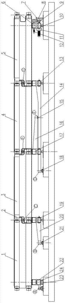
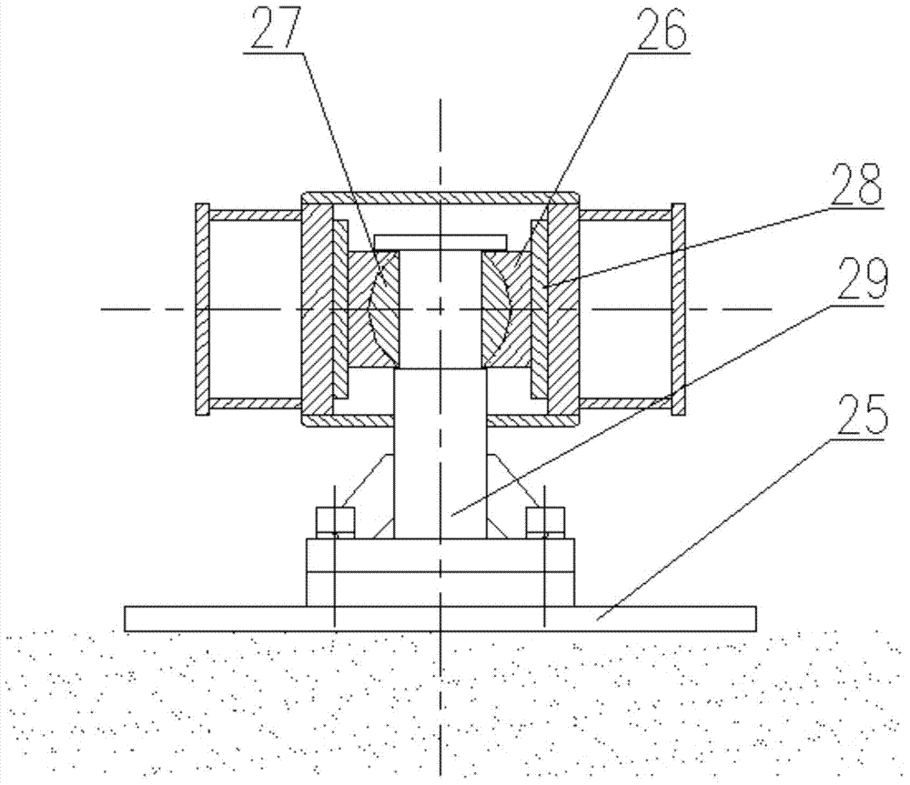
[0017] Attached below figure 1 , 2 , 3, 4, 5 describe an embodiment of the present invention.

[0018] A jointed turnout with a single driving point, with active beam 5, driven beam I1, driven beam II3, and driven beam III4; including trolley I10, trolley II13, trolley III17, trolley IV19 and trolley V22, the The trolley I10, the trolley II13, the trolley III17, and the trolley IV19 are respectively located on the corresponding switch rails 31 provided on the base 25, and the trolley V22 is located on the sliding support 24 provided on the base 25; The first and last ends of the active beam 5 are respectively fixed on the trolley I10 and the trolley II13, and the first and last ends of the driven beam II3 are respectively fixed on the trolley III17 and the trolley IV19; the first and last ends of the driven beam III4 The tail end of the active beam 5 and the head end of the driven beam II3 are respectively overlapped and hinged; the tail end of the driven beam I1 is fixed o...


PUM


Abstract

A single-drive-point joint turnout is provided with a driving beam, three driven beams and five trolleys located on corresponding turning tracks. The beams are in lap joint and hinged and then fixed on the corresponding trolleys. The trolley I is provided with a driving device and a locking device, wherein a positioning device is fixed on a base, the locking device and the positioning device are matched to achieve locking of the trolley I, and the driving device achieves movement of the trolley I. The front end of a long sliding arm is in rigid connection with the trolley II, the rail end of the long siding arm extends to the back portion of the trolley III and is hinged to the base through a sliding rotation pair. The front end of a middle sliding arm is rigid connection with the trolley III, and the tail end of the middle sliding arm extends to the position between the trolley III and the trolley II and is hinged to the long sliding arm through a sliding rotation pair. The front end of the short sliding arm is in rigid connection with the trolley IV, and the rail end of the short sliding arm extends to the back portion of the trolley IV and is hinged to the base through a sliding rotation pair. The rear end of the trolley V is hinged to the base. The manufacture and debugging difficulty of a joint turnout driving and locking system is reduced, and the reliability is improved.

Description

technical field [0001] The invention belongs to the technical field of rail transit turnouts, in particular to an articulating turnout for a maglev transportation system or a straddle-type transportation system, in particular to a single driving point articulating turnout. Background technique [0002] For vehicles that straddle on rails, such as maglev vehicles and straddle vehicles, the switch for switching between two or more fixed rails can be integral or articulated. The integral turnout beam is a steel beam that can be flexed elastically. The main advantage of this kind of turnout lies in its linear continuity and good train passing performance. However, this kind of turnout is limited by the elastic modulus of the material and the deformation coefficient is small. In order to achieve a certain amount of switching, the length of the steel beam is required to be large, and the lateral rigidity due to deformation is small, which may cause a large force when the train pa...

Claims


Application Information

Patent Timeline
IPC IPC(8): B61L5/02
Inventor 吉敏廷牛均宽都武
Owner CHINA RAILWAY BAOJI BRIDGE GRP
Why Eureka
Try Eureka