Plate type metal-rubber shear friction damper

A technology of friction damper and metal rubber, which is applied in the direction of building components, shockproof, etc., can solve the problems of limited use, small vibration deformation energy consumption effect is not obvious, rubber shock absorber aging, etc., to ensure the vibration reduction effect and hysteresis The effect of full curve and large deformation ability

Inactive Publication Date: 2014-04-02
HARBIN INST OF TECH
View PDF9 Cites 8 Cited by
  • Summary
  • Abstract
  • Description
  • Claims
  • Application Information

AI Technical Summary

Problems solved by technology

[0002] As an energy-dissipating element of a multi-story steel frame, the traditional viscous damper has good energy-dissipating performance, but its energy-dissipating effect in small vibration deformation is not obvious, so its use in engineering is limited
The invention proposes a damper,

Method used


Image

  • Plate type metal-rubber shear friction damper
  • Plate type metal-rubber shear friction damper
  • Plate type metal-rubber shear friction damper

Examples


Example Embodiment

[0015] Example 1

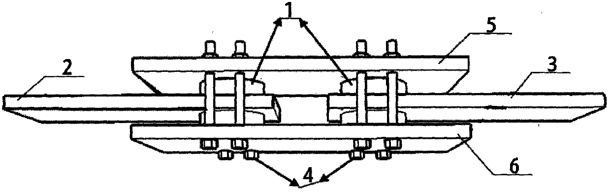
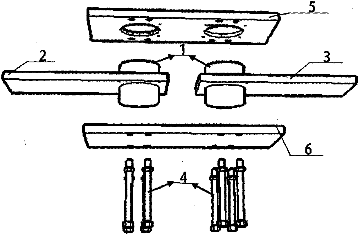
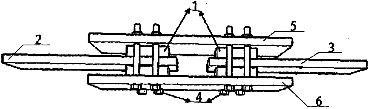
[0016] A plate-type metal-rubber shear friction damper, including two identical cubic metal-rubber blocks 1, left force application plate 2, right force application plate 3, fastening bolts 4, upper clamping plate 5 and lower clamping plate 6 , the left and right force steel plates 2 and 3 have holes of the same size as the two cubic metal rubber blocks 1, and the two cubic metal rubber blocks 1 are respectively placed in the holes of the left and right force force steel plates 2 and 3 Inside, the upper and lower two clamping steel plates 5 and 6 are respectively provided with a plurality of bolt holes and have a dent having the same size as the top surface of the cube metal rubber block 1. The force-applying steel plates 2 and 3 are placed between the upper and lower clamping steel plates 5 and 6, and the space between the cubic metal rubber block 1 and the upper and lower clamping steel plates 5 and 6 passes through the dents on the clamping steel plates ...

Example Embodiment

[0017] Example 2

[0018] The metal rubber block is made by weaving the stretched helical metal wire with good quality in a certain way, and then formed by cold stamping process; the upper and lower clamping steel plates are made of ordinary steel, and a certain number of bolt holes are opened for connection. . The cube (cylindrical) metal rubber block is directly placed in the hole opened by the force steel plate; the cubic metal rubber block and the upper and lower clamping steel plates are bolted by the dent in the middle of the two steel plates and the bolt holes reserved between the steel plates.

[0019] Experiments have proved that the plate-type metal-rubber shear friction damper proposed by the present invention appropriately improves the traditional viscous damper, and can improve the performance of the traditional viscous damper by replacing ordinary rubber with metal rubber. , has the advantages of small vibration deformation, obvious energy consumption, full hyst...


PUM


Abstract

The invention provides a plate type metal-rubber shear friction damper. The plate type metal-rubber shear friction damper comprises two same metal-rubber blocks, a left steel force-application plate, a right steel force-application plate, fastening bolts, an upper steel clamping plate and a lower steel clamping plate. The left and the right steel force-application plate are provided with holes in the size the same with the metal-rubber blocks, and the two metal-rubber blocks are respectively arranged in the holes of the left and the right steel force-application plate. The upper and the lower steel clamping plate are provided with multiple bolt holes and also provided with recesses in the size the same the top surfaces of the metal-rubber blocks. The left and the right steel force-application plate with the metal-rubber blocks are disposed between the upper and the lower steel clamping plate, and the metal-rubber blocks are in bolt fastening with the upper and the lower steel clamping plate through the recesses and the bolt holes formed on the upper and the lower steel clamping plate. The plate type metal-rubber shear friction damper has the advantages of high-and-low temperature resistance, corrosions resistance, ageing resistance, high intensity, impact resistance, long service life and the like.

Description

technical field [0001] The invention relates to the technical field of structural engineering, in particular to a plate-type metal rubber shear friction damper. Background technique [0002] As energy-dissipating elements of multi-story steel frames, traditional viscous dampers have good energy-dissipating performance, but their energy-dissipating effect is not obvious when small vibration deformation occurs, which limits their use in engineering. The invention proposes a damper, which is mainly composed of steel plates and metal rubber blocks, has the vibration damping and buffering performance of rubber, high and low temperature resistance, corrosion resistance, and unlimited shelf life. The technical problems of aging due to changes and environmental pollution. Contents of the invention [0003] The object of the present invention is to provide a plate type metal rubber shear friction damper to solve the above disadvantages. [0004] The purpose of the present inventi...

Claims


Application Information

Patent Timeline
IPC IPC(8): E04B1/98
Inventor 李冀龙欧进萍廖云飞张剑菲王东志
Owner HARBIN INST OF TECH
Why Eureka
Try Eureka