
Sealing plate and sealing hole viscous damper

A technology of viscous damper and dense plate, which is applied in the direction of building components and earthquake resistance, can solve the problems of not considering the dynamic characteristics of the structure, the increase in the number of mechanical parts, and the difficulty of realizing the structural system, so as to reduce the seismic response and improve the reliability. and the effect of high stability and large initial stiffness

Inactive Publication Date: 2013-02-06
SHENYANG JIANZHU UNIVERSITY
View PDF17 Cites 4 Cited by
  • Summary
  • Abstract
  • Description
  • Claims
  • Application Information

AI Technical Summary

Problems solved by technology

[0003] At the beginning of the 20th century, the seismic calculation method proposed by Professor Omori Fangyoshi and the seismic coefficient method proposed by Dr. Sano Toshiki did not consider the dynamic characteristics of the structure. Later, it was called the static theory of seismic design. Rigid building structure, that is, "rigid structural system", but this kind of structural system is difficult to realize, and it is not economical. Only a very small number of important buildings adopt this structural system
However, on the other hand, due to the increase in the number of mechanical parts, the reliability decreases, and the possibility of problems such as failures increases

Method used


Image

  • Sealing plate and sealing hole viscous damper
  • Sealing plate and sealing hole viscous damper
  • Sealing plate and sealing hole viscous damper

Examples


Embodiment Construction

[0017] The present invention will be described in detail below in combination with technical solutions and with reference to the accompanying drawings.

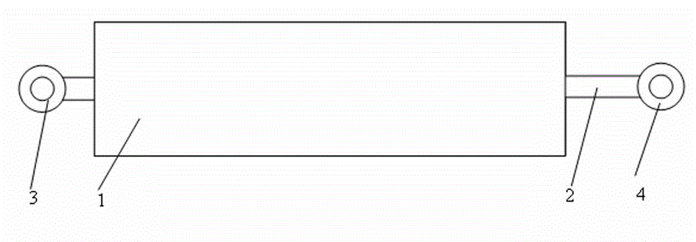
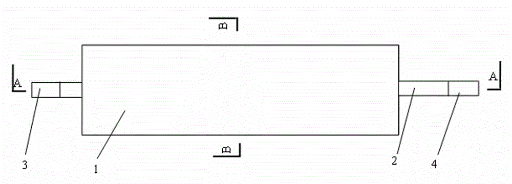
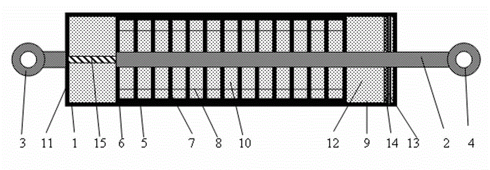
[0018] Such as Figure 1~Figure 4 As shown, a viscous damper with dense plates and dense holes in the present invention includes a main cylinder 1, a guide rod 2, a main cylinder connecting earring 3, an auxiliary cylinder connecting earring 4, an auxiliary cylinder 5, and an auxiliary cylinder end Plate 6, built-in dense plate of auxiliary cylinder 7, dense plate connecting rib 8, sub-cylinder cavity of main cylinder 9, sub-cylinder cavity of auxiliary cylinder 10, end plate of main cylinder 11, viscous liquid 12, sealing ring 13, polyurethane An oil seal 14, a return spring 15 and a fine hole 16. The auxiliary cylinder 5 is arranged in the main cylinder 1 and connected with the main cylinder 1 through a spring. The auxiliary cylinder 5 includes two auxiliary cylinder end plates 6 and Several auxiliary cylinders have built-...


PUM


Abstract

The invention provides a sealing plate and sealing hole viscous damper. The sealing plate and sealing hole viscous damper mainly comprises a main cylinder, a guide rod, a main cylinder connection lug ring, an auxiliary cylinder connection lug ring, an auxiliary cylinder, auxiliary cylinder end plates, auxiliary cylinder built-in sealing plates, sealing plate connection ribs, a main cylinder division cavity, an auxiliary cylinder division cavity, a main cylinder end plate, viscous liquid, a sealing ring, a polyurethane oil seal, a resetting spring, fine sealing hole channels and the like, and is characterized in that the auxiliary cylinder mainly comprises two auxiliary cylinder end plates and a plurality of auxiliary cylinder built-in sealing plates; the auxiliary cylinder built-in sealing plates are arranged in parallel and are connected with one another through the guide rod and the sealing plate connection ribs; the fine sealing hole channels are formed in the auxiliary cylinder built-in sealing plates; pressure limiting valves are arranged on the auxiliary cylinder end plates; the auxiliary cylinder is connected with the main cylinder through a spring; and the sealing ring and the polyurethane oil seal are arranged on one side of the guide rod. The sealing plate and sealing hole viscous damper has the effects and the advantages of large damping force, high initial rigidity, high reliability and stability, simplicity in manufacturing and mounting and convenience in use and can be applied to earthquake resistant design of new building engineering and reinforcement and maintenance of existing engineering.

Description

technical field [0001] The invention relates to a vibration control device for a building structure, in particular to a viscous damper with dense plates and dense holes for building structure vibration control. Background technique [0002] Earthquake disasters are sudden and devastating, which seriously threaten the safety of human life and property. Nearly a thousand destructive earthquakes occur every year in the world, and a major earthquake can cause hundreds of billions of dollars in economic losses, resulting in hundreds of thousands of deaths or serious injuries. my country is located in the two most active seismic belts in the world, and is one of the countries that suffered the most serious earthquake disasters. The casualties caused by the earthquake rank first in the world, and the economic loss is also very huge. The massive destruction and collapse of buildings in earthquakes is the direct cause of earthquake disasters. When an earthquake occurs, ground vibra...

Claims


Application Information

Patent Timeline
Patent Type & Authority Applications(China)
IPC IPC(8): E04B1/98
Inventor 张延年汪青杰徐春一郑怡刘阳
Owner SHENYANG JIANZHU UNIVERSITY
Learn More