Quick positioning parts for steel bar binding

A technology of steel bar binding and positioning parts, which is applied in the direction of construction, building structure, and building material processing, etc. It can solve the problems of low binding accuracy, difficult positioning, time-consuming and labor-intensive rework and rectification, etc., to improve quality and ensure accuracy high rate effect

Active Publication Date: 2016-06-29
CCCC SECOND HARBOR ENG +3
View PDF8 Cites 0 Cited by
  • Summary
  • Abstract
  • Description
  • Claims
  • Application Information

AI Technical Summary

Problems solved by technology

[0002] At present, for the steel cage binding process, especially for the large-volume steel cage binding construction, the design of the binding platform is usually adopted. The workers place the steel bars on the binding platform according to the approximate position required by the design; The pre-marked scale adjusts the binding position of each steel bar one by one; the process of this kind of binding positioning is relatively random, and the binding accuracy is also very low, especially for some steel bars located in a small space, it is difficult to locate them; once there is a deviation in positioning accuracy , the rework and rectification is time-consuming and labor-intensive, which is not conducive to factory-like and standardized construction

Method used


Image

  • Quick positioning parts for steel bar binding
  • Quick positioning parts for steel bar binding
  • Quick positioning parts for steel bar binding

Examples


Embodiment 1

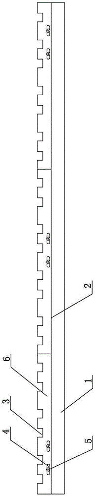
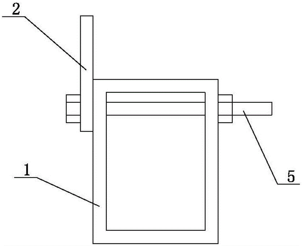
[0023] See figure 1 , figure 2 As shown, the fast positioning member for steel tying of the present invention has a mounting plate 2 for installing corresponding to the steel pipe 1 on the steel cage tying platform. On the upper side of the mounting plate is provided for multiple strips at one time. Multiple positioning slots 3 for binding and positioning the steel bars. The material of the mounting plate in this embodiment is thicker steel plate or other hard materials that are not easily deformed, and a positioning slot suitable for actual construction design needs is made on the mounting plate by a lathe. This kind of fast positioning member for steel bar binding is used to solve the technical problems of narrow space, no separate support system, different steel bar spacing, and quick installation and disassembly in the process of steel cage binding.

[0024] The present invention adopts the design of the positioning card slot. The installation card slot is set according to t...


PUM


Abstract

The invention relates to a quick positioning piece for steel bar binding, in particular to a quick positioning piece for achieving quick positioning on all steel bars to be bonded through positioning clamping grooves. The quick positioning piece is provided with a mounting plate, and a plurality of positioning clamping grooves are formed in one side or two sides on the mounting plate. In the quick positioning piece provided by the invention, the design of the positioning clamping grooves is adopted, the positioning clamping grooves are arranged according to pre-designed arrangement positions and dimension and can be used for positioning before binding the steel bars required to be bonded, by controlling the distances of the steel bars to be bonded through the positioning clamping grooves, accumulated errors produced by the placement of the steel bars are enabled to be eliminated one by one by all the positioning clamping grooves, steel bar mounting can be performed quickly and correctly, the condition that distance deflection of the steel bars can completely meet specification requirements is ensured, and the binding position accuracy of the steel bars are enabled to conform to construction design requirements; the accuracy guarantee rate is high; the steel bar cage binding quality is improved greatly, and steel bar cage binding construction is enabled to be standard and industrialized.

Description

Technical field [0001] The invention relates to a fast positioning part for binding steel bars, in particular to a fast positioning part which realizes the fast positioning of the steel bars to be bound through a positioning slot. Background technique [0002] At present, for the reinforcement cage lashing process, especially for the large-volume reinforcement cage lashing construction, the design of the lashing platform is usually adopted. The workers place the steel bars on the lashing platform according to the approximate position required by the design; then pass the marking on the steel pipe. The pre-marked scale adjusts the binding position of each steel bar one by one; this kind of binding positioning process is relatively random, and the binding accuracy is also very low, especially for some steel bars located in a small space, it is difficult to locate them; once the positioning accuracy deviation occurs , Rework and rectification are time-consuming and labor-intensive, ...

Claims


Application Information

Patent Timeline
Patent Type & Authority Patents(China)
IPC IPC(8): E04G21/12
Inventor 周光强张洪戴书学杨永宏刘经国苏怀平孙志
Owner CCCC SECOND HARBOR ENG
Why Eureka
Try Eureka