
Intercooling pipeline

A technology of cold pipe and pipe body, which is applied in the field of automobile engines, can solve the problems of low negative pressure resistance and achieve the effect of improving negative pressure resistance

Active Publication Date: 2014-04-02
CHERY AUTOMOBILE CO LTD
View PDF8 Cites 0 Cited by
  • Summary
  • Abstract
  • Description
  • Claims
  • Application Information

AI Technical Summary

Problems solved by technology

[0006] In order to solve the problem of low negative pressure resistance of the intercooler pipeline in the prior art, the embodiment of the present invention provides an intercooler pipeline

Method used


Image

  • Intercooling pipeline
  • Intercooling pipeline

Examples


Embodiment 1

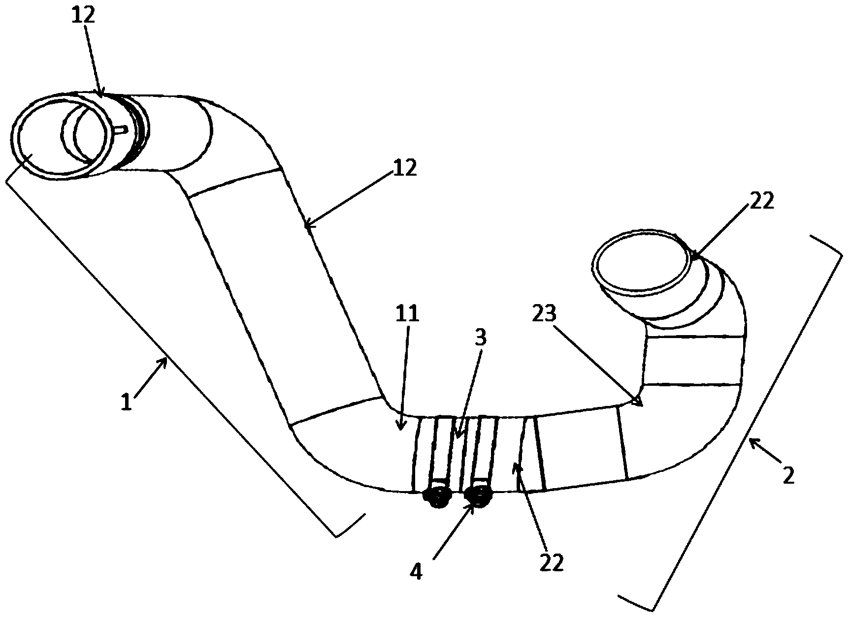
[0037] as attached figure 1 As shown, the embodiment of the present invention provides an intercooling pipeline, the intercooling pipeline includes: a first pipe body 1, a second pipe body 2 and a metal pipe 3, the first pipe body 1, the The metal pipe 3 and the second pipe body 2 are connected in sequence;

[0038] The materials of the first pipe body 1 and the second pipe body 2 are heat-resistant rubber;

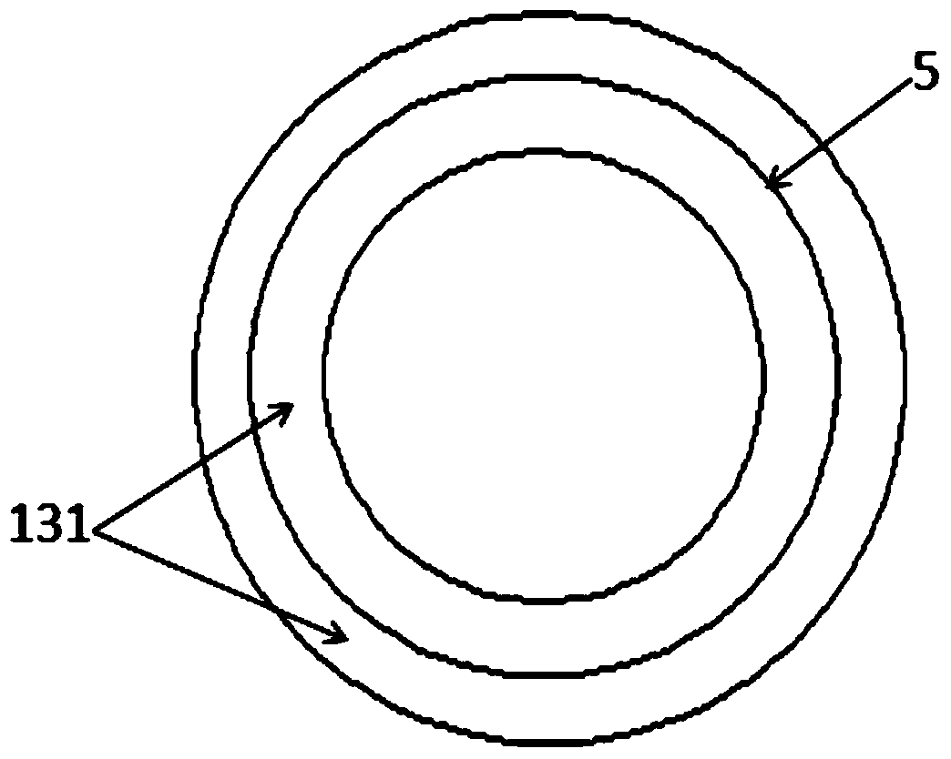
[0039] Both the first pipe body 1 and the second pipe body 2 are provided with wire support bodies 5 inside the pipe walls.

[0040] The use of a high-power engine makes the ambient temperature around it relatively high, so the embodiment of the present invention selects a high-temperature air delivery intercooler pipeline made of heat-resistant material to be arranged between the outlet of the supercharger and the inlet of the intercooler. By selecting heat-resistant rubber as the material of the first pipe body 1 and the second pipe body 2, the intercooler pipeline ca...

Embodiment 2

[0062] The embodiment of the present invention provides an intercooling pipeline, which includes: a first pipe body 1, an aluminum pipe and a second pipe body 2 connected in sequence; the first pipe body 1 and the second pipe body 2 All materials are acrylic rubber. By choosing heat-resistant acrylate rubber as the material of the first pipe body 1 and the second pipe body 2, the intercooler pipeline can be used as a delivery channel for high-temperature air for a long time without deformation when used at 130°C-150°C . Due to the high elasticity of acrylate rubber, the intercooler pipeline can effectively buffer the vibration generated when the engine is working, and attenuate the vibration to achieve the purpose of protecting the intercooler.

[0063] Wherein, both the first pipe body 1 and the second pipe body 2 are composed of a reinforcing section and two connecting sections, and the two connecting sections are respectively located at two ends of the reinforcing section....


PUM


Abstract

An embodiment of the invention provides an intercooling pipeline comprising a first pipe, a metal pipe and a second pipe connected in sequence. Both the first pipe and the second pipe are made of heat-resistant rubber, and metal wire supports are arranged on the inner sides of walls of the first pipe and the second pipe. As the intercooling pipeline is made of the heat-resistant rubber, the intercooling pipeline can be used as a high-temperature air delivery passage for a long time without any distortion. As the heat-resistant rubber has the high elasticity, the intercooling pipeline can buffer vibration generated during operation of an engine effectively, and can attenuate vibration to protect an intercooler. By the aid of the metal wire supports arranged on the inner sides of the walls of the first pipe and the second pipe, the intercooling pipeline is reinforced, negative-pressure resistance capacity of the intercooling pipeline is improved, and sunk-down of the intercooling pipeline due to suction is avoided. Therefore, the intercooling pipeline has both high negative-pressure resistance capacity and vibration attenuation capacity.

Description

technical field [0001] The invention relates to the field of automobile engines, in particular to an intercooling pipeline. Background technique [0002] The intercooler pipeline is an important component of an automobile supercharged engine. It is often connected between the outlet of the supercharger and the inlet of the intercooler as a gas passage for delivering the high-temperature air in the supercharger to the intercooler. cooling in the container. Since the supercharged engine will generate vibration during operation, the vibration will be transmitted to the intercooler through the intercooler pipeline, which may easily cause damage to the intercooler. Therefore, it is necessary to provide an intercooling pipeline capable of effectively damping the vibration. [0003] At present, the intercooler pipeline used for high-temperature air transportation is generally made of rubber material. The two ends of the intercooler pipeline are respectively provided with an inter...

Claims


Application Information

Patent Timeline
Patent Type & Authority Applications(China)
IPC IPC(8): F16L11/08F16L33/02F02B29/04
CPCY02T10/146F02B29/04Y02T10/12
Inventor 薛鹏蒲恒高必勇叶华华
Owner CHERY AUTOMOBILE CO LTD
Learn More