Rotary base

A technology of rotating base and chassis, which is applied in the direction of lighting auxiliary devices, lighting and heating equipment, components of lighting devices, etc. It can solve the problems of difficult selection of bearings of suitable size, high manufacturing cost of rotating base, and inflexible base rotation. Achieve the effect of less parts, low manufacturing cost, simple and stable structure

Active Publication Date: 2014-04-02
OCEANKING DONGGUAN LIGHTING TECH +2
View PDF6 Cites 3 Cited by
  • Summary
  • Abstract
  • Description
  • Claims
  • Application Information

AI Technical Summary

Problems solved by technology

Rotating lighthouses are generally equipped with rotating bases to achieve the effect of rotating lighting in all directions. The rotating bases of existing rotating lighthouses are usually only composed of chassis and trays without using bearings. This type of base is not flexible in rotation and has high friction. It is easy to wear and tear; although some have built-in balls to ensure the flexible rotation of the tray and reduce friction, the manufacturing cost of this type of rotating base is high
Some rotating bases use large bearings to ensure that the lighthouse can rotate smoothly, but the price of large bearings is high, and it is difficult to choose bearings of suitable size for larger lighthouses

Method used


Image

  • Rotary base
  • Rotary base
  • Rotary base

Examples


Embodiment 1

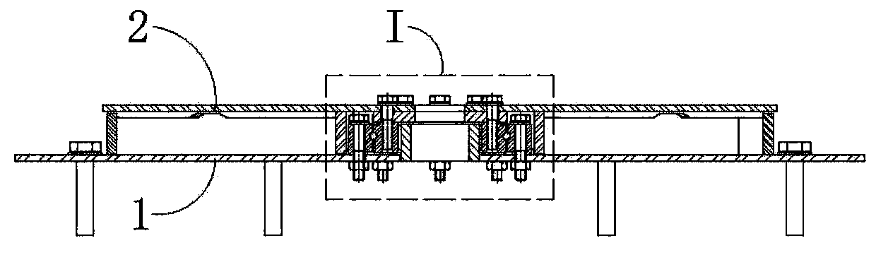
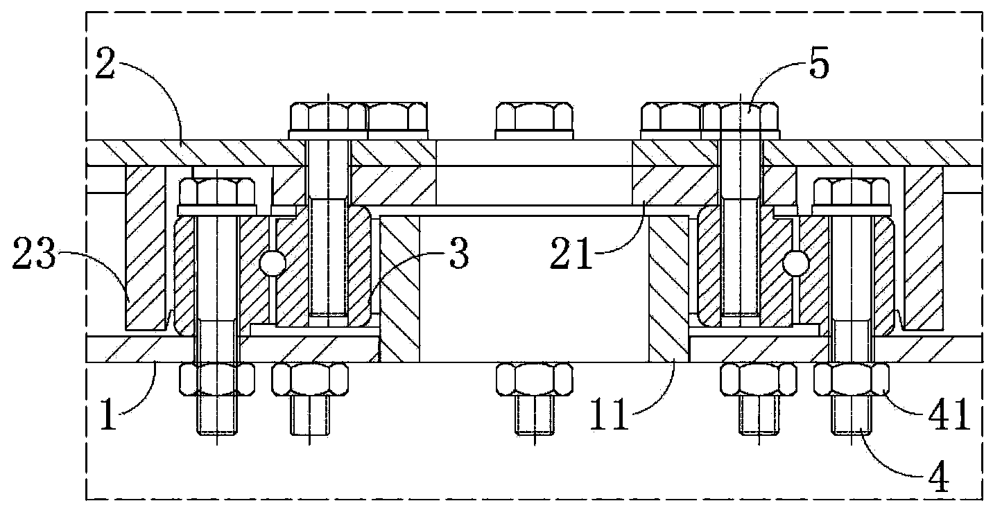
[0034] Embodiment one: see Figure 2A and image 3 , the bearing is a radial bearing 3. Specifically, the outer ring of the radial bearing 3 is uniformly provided with a first through hole 31, and the chassis 1 is provided with a second through hole 13 corresponding to the first through hole 31 (see Figure 4 ), the first bolt 4 penetrates the first through hole 31 and the second through hole 13 and locks the nut 41; The backing ring 21 that the first bolt 4 and the pallet 2 interfere with each other; the inner ring of the radial bearing 3 is evenly provided with screw holes 32, and the tray 2 and the backing ring 21 are respectively provided with The third through hole 22 and the fourth through hole 211 corresponding to the screw hole 32 (see Figure 7 ), the second bolt 5 passes through the third through hole 22 and the fourth through hole 211 and is screwed into the screw hole 32 . What the radial bearing 3 drills on its inner and outer rings is all through holes, witho...

Embodiment 2

[0035] Embodiment 2 (not shown): the bearing is a thrust bearing. Specifically, the surfaces of the two thrust washers of the thrust bearing are respectively uniformly provided with screw holes around the circumference, and the chassis and the tray are respectively provided with through holes corresponding to the screw holes, and the bolts pass through the through holes and Screw it into the screw hole. Thrust bearings support heavier light towers.

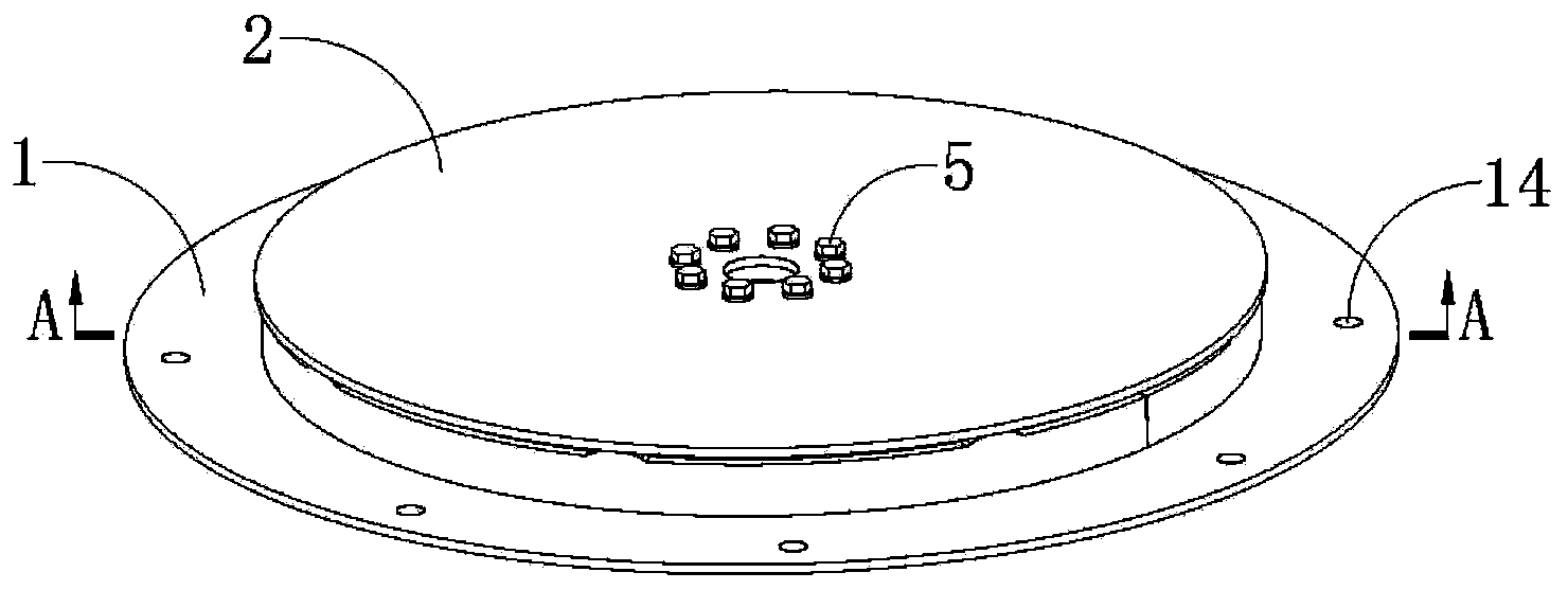
[0036] see Figure 4 or Figure 5 Further, fifth through holes 14 for positioning the chassis 1 are uniformly provided on the surface of the chassis 1 . The chassis 1 can be fixed on the base using fasteners.


PUM


Abstract

The invention provides a rotary base. The rotary base comprises a base plate, a tray and a bearing arranged on the base plate, wherein a positioning shaft used for limiting the position of the bearing is arranged at the central position of the base plate; the bearing is sleeved on the positioning shaft; one end of the bearing is connected with the base plate; the tray is placed on the bearing and is connected with the other end of the bearing; a first annular flange which is coaxial with the positioning shaft and is used for balancing the tray is also arranged on the surface, opposite to the tray, of the base plate; a second annular flange which is used for balancing the tray and is coaxial with the positioning shaft is arranged on the surface, opposite to the base plate, of the tray; the diameter of the second annular flange is greater than or smaller than that of the first annular flange; the end surfaces of the first annular flange and the second annular flange are in uniformly distributed multi-point concave and convex structures. The bearing can be a radial bearing or a thrust bearing; the tray can support a lighthouse; according to the rotary base, a small bearing can play the role of a large bearing, so that the manufacturing cost is reduced; the rotary base has a simple and stable structure, few components and low manufacturing cost, and can drive the lighthouse to rotate at 360 degrees smoothly.

Description

technical field [0001] The invention relates to the technical field of rotating bases, in particular to the improvement of the structure of the rotating base of a lighthouse. Background technique [0002] In many occasions, it is necessary to use rotating lighthouses, such as night road construction, night police duty, concert venues, etc. Rotating lighthouses are generally equipped with rotating bases to achieve the effect of rotating lighting in all directions. The rotating bases of existing rotating lighthouses are usually only composed of chassis and trays without using bearings. This type of base is not flexible in rotation and has high friction. It is easy to wear and tear; although some have built-in balls to ensure that the tray can rotate flexibly and reduce friction, the manufacturing cost of this type of rotating base is high. Some rotating bases use large bearings to ensure that the lighthouse can rotate smoothly, but the price of large bearings is high, and it ...

Claims


Application Information

Patent Timeline
IPC IPC(8): F21V21/30
Inventor 周明杰费诗超
Owner OCEANKING DONGGUAN LIGHTING TECH
Why Eureka
Try Eureka