Drum-type probe device for ultrasonic testing
A drum-type, ultrasonic technology, applied to measuring devices, using sound waves/ultrasonic waves/infrasonic waves for material analysis, instruments, etc., can solve problems such as increased detection costs, missed detection, direction changes, etc., to ensure service life and reduce wear Effect
- Summary
- Abstract
- Description
- Claims
- Application Information
AI Technical Summary
Problems solved by technology
Method used
Image

Examples
Embodiment Construction
[0024] The present invention will be further described in detail below in conjunction with the accompanying drawings and embodiments.
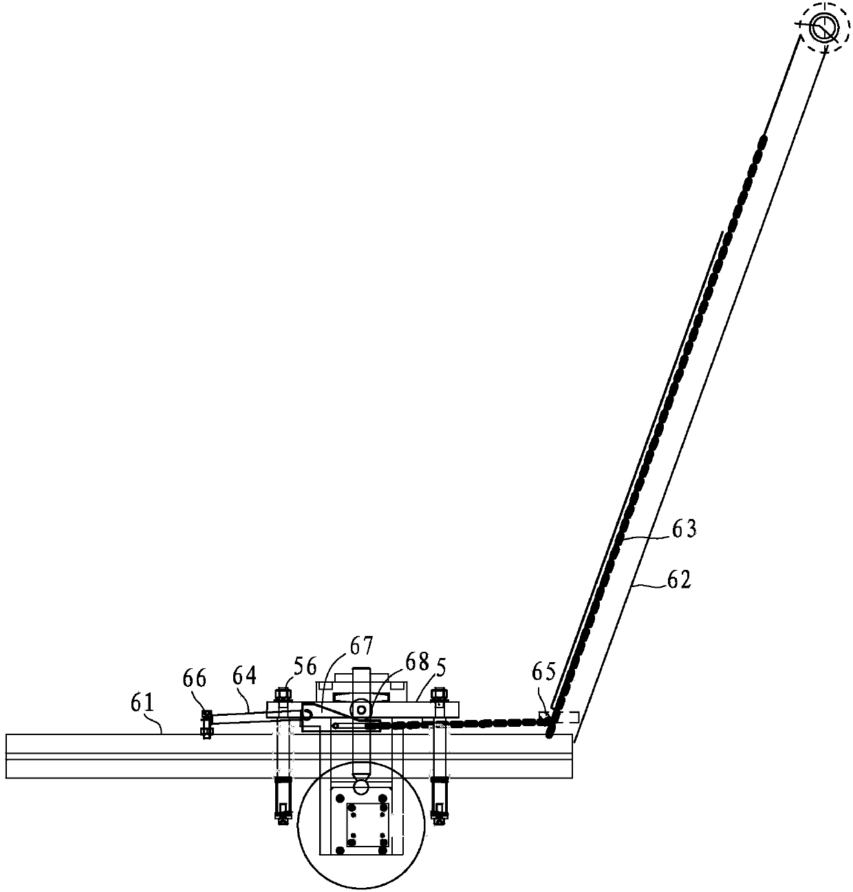
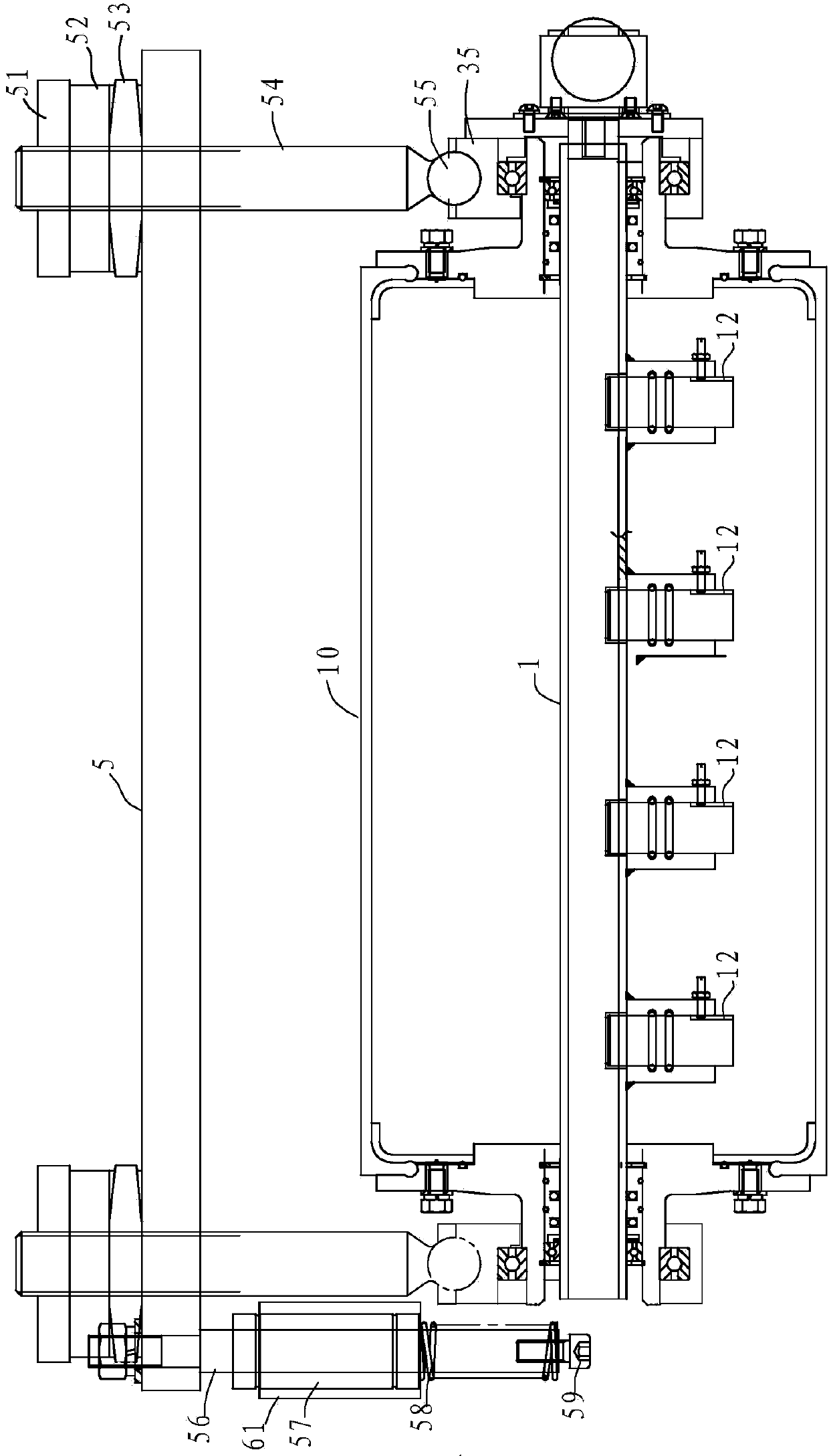
[0025] Such as figure 1 and figure 2 As shown, the ultrasonic detection drum probe device in this embodiment includes a central axis 1, a probe 12, an inner flange 1a, an outer flange 1b, an outer membrane 10, a motor, a reducer 37, a car body, a platform 5, and a slider 67, extension spring 64 and traction cable 63.
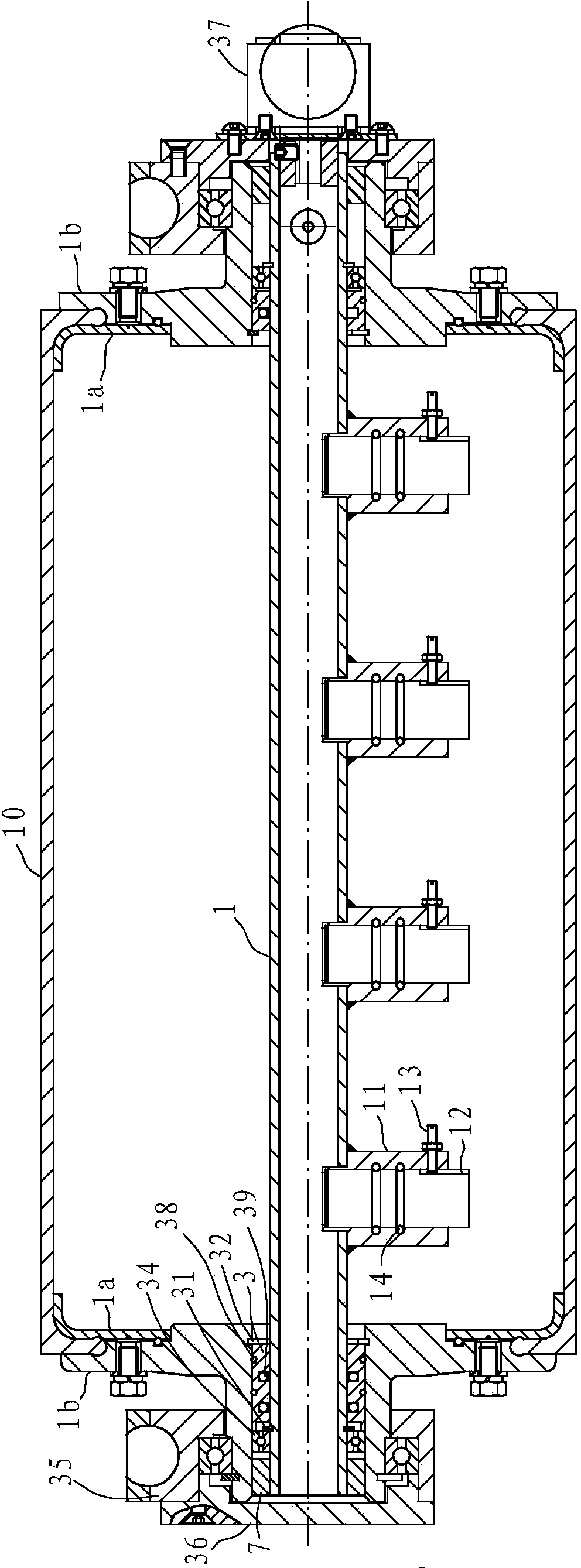
[0026] combine image 3 and Figure 4 As shown, the central shaft 1 is hollow for cables to pass through and sealed at both ends. Four through holes are opened on one side of the outer wall, and a mounting seat 11 is arranged on the through holes; the inner wall of the mounting seat 11 has an annular groove near the central shaft. The annular groove is provided with a sealing ring 14, and there are four probes 12, and each probe 12 is hermetically arranged on the mounting base 11 and exposes the emitting end surface; specif...
PUM
 Abstract
Description
Claims
Application Information