Projection-type integrated imaging 3D display device

An integrated imaging and display device technology, applied in photography, image communication, stereo photography, etc., can solve the problems of reducing 3D viewing angle, crosstalk, and increasing 3D depth of field, so as to increase 3D viewing angle and avoid crosstalk images Effect

Active Publication Date: 2014-04-02
SICHUAN UNIV
View PDF3 Cites 12 Cited by
  • Summary
  • Abstract
  • Description
  • Claims
  • Application Information

AI Technical Summary

Problems solved by technology

The integrated imaging 3D display of focusing mode is carried out in the way of projection. The micro-image array is directly projected in the space without the diffuse reflection effect of the projection screen on the light, which can effectively reduce the divergence angle of the pixels in the micro-image array, thereby increasing the Large 3D depth of field, but because the micro-image array projected by the projector is aligned with the center of the micro-lens array and has the same pitch, the light rays emitted by the pixels far away from the center of the micro-image array have a larger inclination angle, as shown in the attached figure 1 As shown in the A pixel in the picture, it will be refracted by adjacent lens elements, which will cause serious crosstalk and reduce the 3D viewing angle. The obtained 3D viewing angle is shown in the attached figure 2 shown in the gray area in the

Method used


Image

  • Projection-type integrated imaging 3D display device
  • Projection-type integrated imaging 3D display device
  • Projection-type integrated imaging 3D display device

Examples


Embodiment Construction

[0024] A typical embodiment of a projection type integrated imaging 3D display device of the present invention is described in detail below, and the present invention is further described in detail. It is necessary to point out that the following examples are only used to further illustrate the present invention, and should not be construed as limiting the scope of protection of the present invention. Those skilled in the art make some non-essential improvements to the present invention according to the above-mentioned content of the present invention. and adjustment, still belong to the protection scope of the present invention.

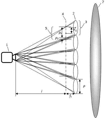
[0025] The present invention provides a projection type integrated imaging 3D display device, as shown in the attached image 3 As shown, the apparatus includes a projector, a microlens array and an imaging objective. The micro-image array is directly projected in the space by the projector, and the distance between the micro-image array and the mi...


PUM


Abstract

The invention discloses a projection-type integrated imaging 3D (three-dimensional) display device. The device comprises a projector, a micro-lens array and an imaging objective. A micro-image array is directly projected into a space by the projector; the spacing between the micro-image array and the micro-lens array is enabled to be equal to the focal length of the micro-lens array; according to an edge of the projector and edges of lens elements, effective pixel regions of image elements are set; according to the positions of the image elements in the micro-image array, the offsets between the centers of the image elements and the centers of the corresponding lens elements are set; light emitted by pixels in the effective pixel region of each image element is retracted by the micro-lens array and the imaging objective so as to implement large-view-angle integrated imaging 3D display.

Description

technical field [0001] The present invention relates to integrated imaging technology, in particular to a projection type integrated imaging 3D display device. Background technique [0002] Integrated imaging includes two processes of shooting and display. The shooting process uses a microlens array to shoot 3D scenes. The microlens array is composed of a series of "fly's eye"-like lens elements arranged at equal intervals in the horizontal and vertical directions. All lens elements have the same imaging function, and record the information of different angles of the three-dimensional scene on the recording film located at the back focal plane of the micro-lens array to form a micro-image array. The display process is the inverse process of the shooting process. The microlens array and the microimage array are precisely coupled with the same parameters as the shooting. The front and rear of the microlens array reconstructs a 3D image that is exactly the same as the 3D scene...

Claims


Application Information

Patent Timeline
Patent Type & Authority Applications(China)
IPC IPC(8): G03B35/24G02B27/22H04N13/04
Inventor 邓欢王琼华熊召龙罗成高李述利
Owner SICHUAN UNIV
Why Eureka
Try Eureka