
Method for adjusting and positioning thermal imager for use in thermal imaging monitoring of liquefied natural gas (LNG) storage tank

A technology of liquefied natural gas and thermal imaging camera, which is applied in radiation pyrometry, instruments, measuring devices, etc., can solve the problems of lowering the temperature of the side wall of the storage tank, changing the temperature field of the storage tank, and endangering the safety of the storage tank.

Inactive Publication Date: 2014-04-02
TIANJIN UNIV
View PDF5 Cites 1 Cited by
  • Summary
  • Abstract
  • Description
  • Claims
  • Application Information

AI Technical Summary

Problems solved by technology

Once the steel inner tank is partially cracked, the insulation layer fails, and the concrete on the outer wall of the storage tank is damaged, it will cause the temperature field of the storage tank to change, reduce the local temperature of the side wall of the storage tank, and endanger the safety of the storage tank.

Method used


Image

  • Method for adjusting and positioning thermal imager for use in thermal imaging monitoring of liquefied natural gas (LNG) storage tank
  • Method for adjusting and positioning thermal imager for use in thermal imaging monitoring of liquefied natural gas (LNG) storage tank
  • Method for adjusting and positioning thermal imager for use in thermal imaging monitoring of liquefied natural gas (LNG) storage tank

Examples


Embodiment Construction

[0015] Below in conjunction with accompanying drawing and specific embodiment the present invention is described in detail:

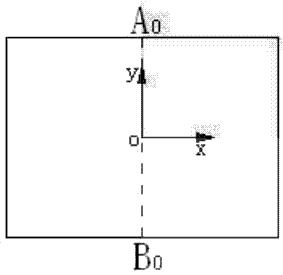
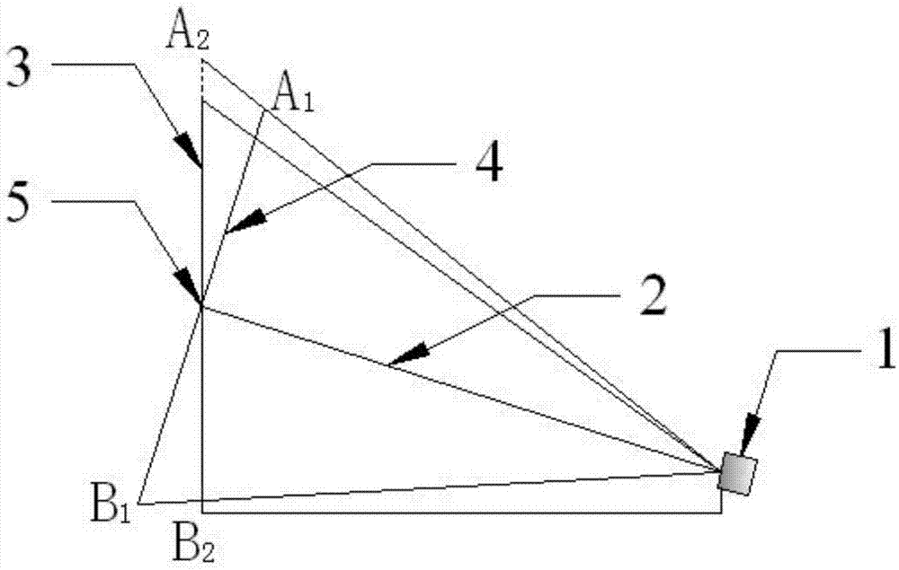
[0016] As shown in the accompanying drawings, the method for adjusting and positioning a thermal imager for thermal imaging monitoring of a liquefied natural gas storage tank according to the present invention comprises the following steps:

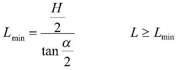
[0017] (1) Determine the installation distance of the infrared thermal imager according to the field of view angle of the infrared thermal imager 1, and the calculation formula for the installation distance is:

[0018] L min = H 2 tan α 2 L ≥ L ...


PUM


Abstract

The invention discloses a method for adjusting and positioning a thermal imager for use in thermal imaging monitoring of a liquefied natural gas (LNG) storage tank. The method comprises the following steps: (1) determining the mounting distance of the thermal imager according to the field angle of the thermal imager; (2) setting the mounting height of the thermal imager according to site requirements; (3) arranging a point heat source at a position accounting for a half of the height of the storage tank, and starting the infrared thermal imager, wherein the thermograph shooting center of the infrared thermal imager is coincided with the set point heat source; (4) converting the coordinate of an upper height boundary point and a lower height boundary point on the middle axis of a thermograph shot by the infrared thermal imager along a vertical direction into height coordinates on the outer wall of the storage tank; (5) keeping the inclination angle of the infrared thermal imager invariable, and moving the infrared thermal imager by a preset distance along the vertical direction to allow the thermal infrared image to shoot an image in the height direction of the storage tank at one time. By adopting the method, all heights of LNG storage tanks can be detected, and the temperature field change of the outer wall of the storage tank is found in time.

Description

technical field [0001] The invention relates to an infrared thermal imager positioning device, in particular to a thermal imager attitude adjustment and positioning method for LNG storage tank monitoring. Background technique [0002] Liquefied natural gas (LNG) storage tank is an essential gas storage container for the transportation and storage of liquefied natural gas. In recent years, the research and development of LNG storage tanks is developing towards large capacity. The LNG storage tank is a composite facility consisting of a steel inner tank containing low-temperature LNG liquid and a concrete outer tank that provides normal operating environment and protection functions. Once the steel inner tank is partially cracked, the insulation layer fails, and the concrete on the outer wall of the storage tank is damaged, it will cause the temperature field of the storage tank to change, reduce the local temperature of the side wall of the storage tank, and endanger the safe...

Claims


Application Information

Patent Timeline
IPC IPC(8): G05D3/12G01J5/02
Inventor 章青赵磊石云飞吴楠
Owner TIANJIN UNIV
Learn More