Conducting ring locating technology of high-power and low-voltage motor

A conductive ring, low-voltage technology is applied in the field of positioning and installation technology of the conductive ring, which can solve the problems of waste of raw materials, increased manufacturing cost of the motor, inaccurate positioning of the conductive ring and the busbar, etc., to achieve accurate spacing, improve production efficiency, The effect of saving installation and positioning time

Active Publication Date: 2014-09-24
CSIC ELECTRICAL MACHINERY SCI & TECH
View PDF6 Cites 0 Cited by
  • Summary
  • Abstract
  • Description
  • Claims
  • Application Information

AI Technical Summary

Problems solved by technology

[0003] The invention provides a conductive ring positioning process for a high-power low-voltage motor, which solves the technical problems of waste of raw materials and increased manufacturing cost of the motor due to inaccurate positioning of the conductive ring and busbar

Method used


Image

  • Conducting ring locating technology of high-power and low-voltage motor
  • Conducting ring locating technology of high-power and low-voltage motor
  • Conducting ring locating technology of high-power and low-voltage motor

Examples


Embodiment Construction

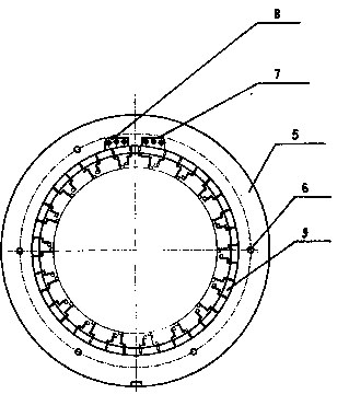
[0019] A conductive ring positioning process for a high-power low-voltage motor, comprising the following steps:

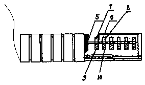
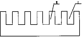
[0020] The first step is to process the conductive ring positioning slots 1 at equal intervals on the rectangular conductive ring positioning card. The number of conductive ring positioning slots 1 is equal to the number of conductive rings of high-power and low-voltage motors, and the adjacent The spacing 2 between the positioning grooves 1 of the two conductive rings is the positioning spacing;

[0021] The second step is to process the positioning arc surface 11 at the bottom of the rectangular bus bar positioning plate, so that the radian of the positioning arc surface 11 is the same as the outer arc surface of the conductive ring of the high-power low-voltage motor, and process it on the bus bar positioning plate Exit the bus bar positioning hole 4 and another bus bar positioning hole 12, so that the spacing between the two bus bar positioning holes is equal ...


PUM


Abstract

The invention discloses a conductive ring positioning process for a high-power low-voltage motor, which solves the problems of waste of raw materials and increased manufacturing cost of the motor caused by inaccurate positioning of the conductive ring and busbar. The method includes the following steps: machining out conductive ring positioning slots (1) at equal intervals on the rectangular conductive ring positioning card plate; machining two bus bar positioning holes (4) on the bus bar positioning plate; placing the first bus bar The positioning plate is connected to the screw rod (6) through the hole (3) through the stud, so that the positioning arc surface (11) at the bottom of the positioning plate of the first busbar is movably matched with the outer arc surface of the first conductive ring (9) , and align the first conductive ring bus bar (7) with a bus bar positioning hole (4) on the first bus bar positioning plate; clamp the conductive ring positioning clamp plate on the first conductive ring and the second conductive ring on the outer circle of . The invention saves the installation and positioning time of the conductive ring, and enables accurate positioning of the three groups of busbars in the circumferential direction and the distance between the axial directions.

Description

technical field [0001] The invention relates to a positioning and installation process of a conductive ring with a busbar at the stator end of a high-power low-voltage motor. Background technique [0002] High-power low-voltage motors often adopt a conductive ring structure with busbars. When the conductive ring is connected to the winding, the traditional visual inspection of the center line and the deformation of the welding process often make the lateral spacing between the busbars and the conductive ring The axial distance between the conductive ring and the conductive ring is not easy to grasp accurately, which often leaves a series of problems in the connection of the busbar in the subsequent outlet box. If the deviation is too large, the original copper bar will be discarded, and a new copper bar needs to be remade according to the existing situation, which will increase the workload, cause waste of valuable production raw materials, increase the manufacturing cost ...

Claims


Application Information

Patent Timeline
Patent Type & Authority Patents(China)
IPC IPC(8): H02K15/00
Inventor 张蕊莉王晓勤师艳平
Owner CSIC ELECTRICAL MACHINERY SCI & TECH
Why Eureka
Try Eureka