Machining device for cable with metal sheath structure

A processing device and metal sheath technology, which is applied in the direction of dismantling/armoring cable equipment, etc., can solve the problems of inability to peel off a large length, easy to damage the cable core, and high labor intensity, so as to reduce labor intensity and improve stripping efficiency. , Improve the effect of stripping efficiency and precision

Active Publication Date: 2014-04-02
JIANGSU HENGTONG WIRE & CABLE TECH
View PDF5 Cites 0 Cited by
  • Summary
  • Abstract
  • Description
  • Claims
  • Application Information

AI Technical Summary

Problems solved by technology

The main problems are low efficiency, easy damage to the cable core,

Method used


Image

  • Machining device for cable with metal sheath structure
  • Machining device for cable with metal sheath structure
  • Machining device for cable with metal sheath structure

Examples


Embodiment

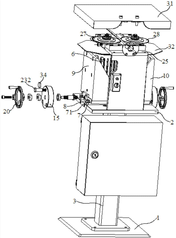
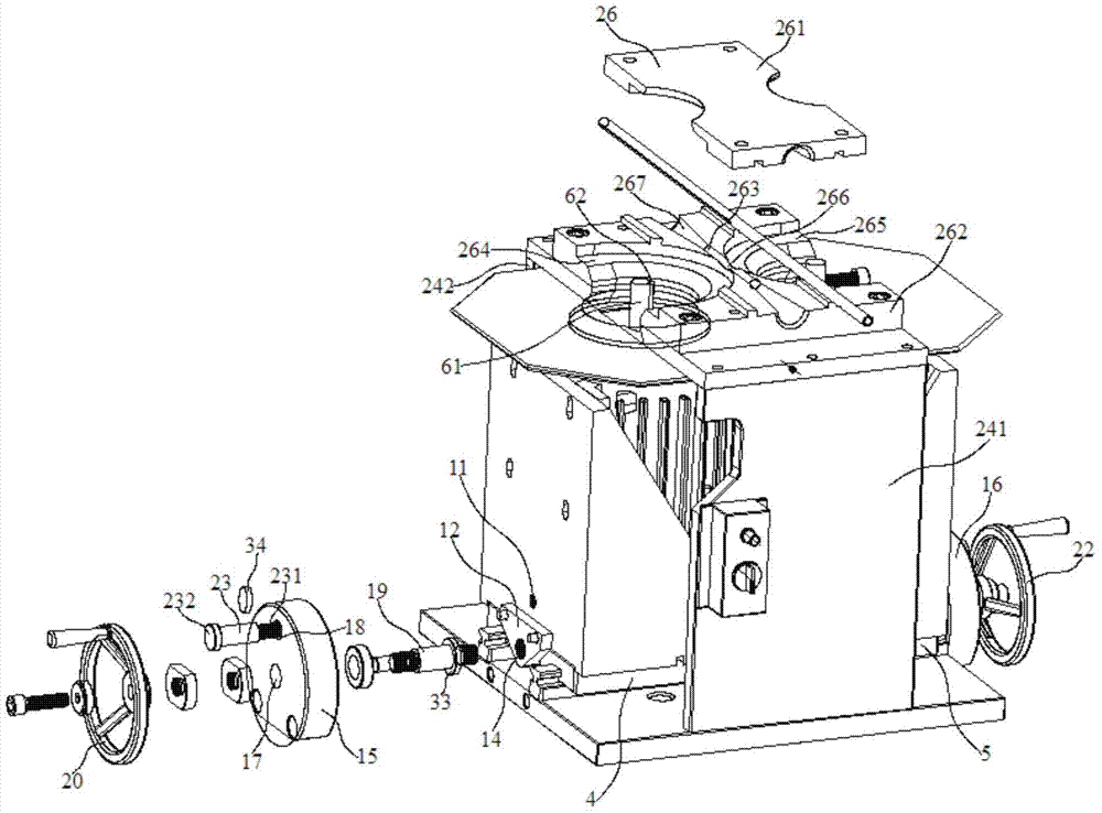
[0029] Embodiment: A processing device for cables with a metal sheath structure, including: a fixed base plate 2, left and right motor brackets 4, 5 and 2 motors 6; one of the 2 motors 6 is installed on the left motor bracket 4, and the other is installed on the right motor bracket 5, the respective lower surfaces of the left and right motor brackets 4 and 5 are fixed with two sliders 7 in parallel, and the fixed bottom plate 2 is provided with two line rails in parallel 8. The line rails 8 are sequentially embedded in the grooves 71 of the sliders 7 of the left and right motor brackets 4 and 5, and the left and right motor brackets 4 and 5 are respectively fixed with adjusting screw holes 11 on their outer sides. Right baffle plate 9,10, the outer sides of this left and right baffle plate 9,10 are respectively fixed with left and right connecting plates 12,13 with drive screw holes 14, and described left and right connecting plates 12,13 are located in two Between the line ra...


PUM


Abstract

The invention discloses a machining device for a cable with a metal sheath structure. The machining device comprises a base, a fixing bottom plate and two motors, wherein two sliding blocks are fixed in parallel on the lower surfaces of left and right motor brackets; left and right baffles with adjusting screw holes are respectively fixed on the outer sides of the left and right motor brackets; left and right connecting plates with driving screw holes are respectively fixed on the outer sides of the left and right baffles; the left and right connecting plates are positioned between two line tracks and the driving screw holes are formed below the left and right motor brackets; round grooves are formed in end surfaces, opposite to the left and right baffles, of the left and right fixing bases; two springs are respectively sleeved upon screw rods of two limiting bolts and are positioned between corresponding left and right fixing bases and left and right baffles; scrap removing mechanisms are fixed on both sides of a guide base; the scrap removing mechanisms consist of fixing blocks and brushing hair. By adopting the machining device, the difficulties in cutting and peeling off a metal protecting layer of the metal sheath cable in the detection, combination and mounting process are solved, the peeling efficiency is improved, and metal layer peeling off of large length is achieved.

Description

technical field [0001] The invention relates to a cable processing device, in particular to a processing device for cables with a metal sheath structure. Background technique [0002] In order to meet the requirements of electromagnetic field shielding and anti-mechanical damage in various complex environments, wire and cable are equipped with copper, aluminum, steel and other metal materials or their alloys in the product design and manufacturing process. The metal shielding sheath composed of materials, that is, the cable metal sheath (also known as the metal sheath), the metal sheath is wrapped with various metal strips, longitudinally wrapped, welded into a tubular or thin round wire wrapped and other structures The form is set on the outer layer of the cable core. For cables with such a metal sheath, in the process of manufacture, installation and maintenance, the metal sheath needs to be cut and stripped before the cable core is inspected, spliced ​​and installed. Du...

Claims


Application Information

Patent Timeline
IPC IPC(8): H02G1/12
Inventor 余建朝王国权沈建新李宁范建华孙明华曹卫忠刘党荣
Owner JIANGSU HENGTONG WIRE & CABLE TECH
Why Eureka
Try Eureka