Compression-resistant and stretch-resistant heat dissipation type cable
A heat-dissipating, anti-stretching technology, applied in the direction of insulated cables, cables, circuits, etc., can solve the problems of shortened life, general pressure resistance, easy damage, etc., to achieve the effect of protecting the wire core
- Summary
- Abstract
- Description
- Claims
- Application Information
AI Technical Summary
Problems solved by technology
Method used
Image
Examples
Embodiment 1
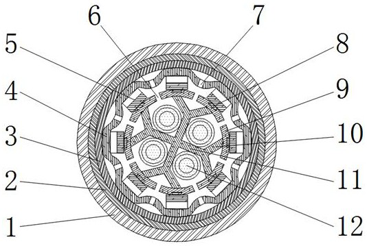
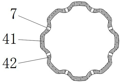
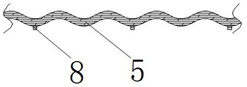
[0036] Such as figure 1The heat-dissipating cable shown is a compression-resistant and tensile-resistant cable, including at least two cores 12 (four cores 12 are shown in the figure) arranged at the cable core and a function of being sleeved on the outside of the cable core in turn. Layer and outer sheath 1, the core 12 includes a conductor, an insulating layer and a shielding layer that are sheathed in sequence from the inside to the outside; the cable core is provided with a separation support frame 11, and the separation support frame 11 includes a wire The cores 12 have one-to-one corresponding dividers, and a divider is provided between every two adjacent cores 12, and each divider is connected to two oblique support bars 10 at one end facing away from the cable axis. , and the distance between these two oblique support bars 10 gradually increases outwards from the connection end with the partition bar, and the outer end of each of the oblique support bars 10 is connecte...
Embodiment 2
[0041] The difference between this embodiment and embodiment 1 is:
[0042] In this embodiment, the wire core 12 and the spacer strips are twisted together, and the arc-shaped support strips 9 , the wave-shaped buffer strips 5 and the compression-resistant sheath 4 all extend helically along the length direction of the cable. This setting can greatly enhance the strength of the cable, and improve the mechanical properties of the cable such as compression resistance and tensile resistance.
[0043] Others are with embodiment 1.
Embodiment 3
[0045] The difference between this embodiment and embodiment 1 is:
[0046] In this example, if Figure 5 As shown, a gap cavity 14 extending along the length direction of the cable is formed between each concave arc portion 42 and the functional layer, and a reinforcing rope 15 extending along the length direction of the cable is arranged in the gap cavity 14 . The reinforcing rope 15 can be made of nylon material, which can enhance the tensile and compressive strength of the cable.
[0047] In this example, if Figure 5 As shown, the space between the spacer support frame 11 , the oblique support bar 10 , the arc support bar 9 , the wave buffer bar 5 , the anti-pressure sheath 4 and the outside of the wire core 12 is filled with a filler 16 . The filler 16 may use flame retardant materials and / or other functional materials, so as to improve the flame retardant performance and / or other performances of the cable.
[0048] In this embodiment, the first functional layer 2 is ...
PUM
 Abstract
Description
Claims
Application Information
 - R&D
- Intellectual Property
- Life Sciences
- Materials
- Tech Scout
- Unparalleled Data Quality
- Higher Quality Content
- 60% Fewer Hallucinations
Browse by: Latest US Patents, China's latest patents, Technical Efficacy Thesaurus, Application Domain, Technology Topic, Popular Technical Reports.
© 2025 PatSnap. All rights reserved.Legal|Privacy policy|Modern Slavery Act Transparency Statement|Sitemap|About US| Contact US: help@patsnap.com


