
LAS signal control unit based on arm Cortex-M3

A signal control unit and signal technology, applied to the signal indicator on the vehicle, railway signal, railway signal and safety, etc., can solve the problem that the shunting driver cannot judge whether the call is normal or not

Active Publication Date: 2015-08-19
天津七一二移动通信有限公司
View PDF2 Cites 0 Cited by
  • Summary
  • Abstract
  • Description
  • Claims
  • Application Information

AI Technical Summary

Problems solved by technology

[0002] At present, in the railway shunting system, in order to ensure the safety of the shunting driver, the shunting operator needs to use a handheld device to guide the operation. The shunting operator must keep talking with the shunting driver at all times to ensure that the shunting driver Shunting is safe. The shunting driver judges whether the communication link with the shunting man is maintained by whether he is talking. When the shunting driver cannot hear the shunting man’s speech, the shunting driver cannot judge whether the call is normal.
[0003] UIC (European Union of Railways) proposed in FRS (Function Requirement Specification) and SRS (System Requirement Specification) that Cab Radio equipment should have Shunting Mode (shunting mode), in which LAS (link confirmation signal) is used to prompt shunting drivers The communication link with the shunting operator is intact. To realize the above requirements, there must be corresponding equipment. At present, there is no manufacturer in the domestic shunting system that produces such a device for detecting this signal, and there is no relevant technical report in the literature.

Method used


Image

  • LAS signal control unit based on arm Cortex-M3
  • LAS signal control unit based on arm Cortex-M3
  • LAS signal control unit based on arm Cortex-M3

Examples


Embodiment Construction

[0035] In order to understand the present invention more clearly, describe the present invention in detail in conjunction with accompanying drawing and embodiment:

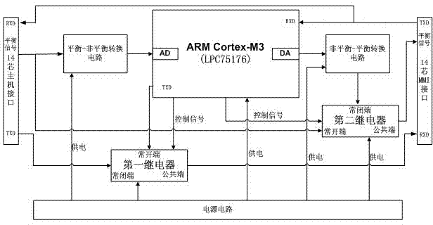
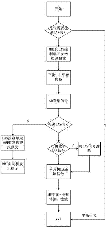
[0036] as attached Figure 1 to Figure 8 As shown, the LAS signal control unit based on ARM Cortex-M3, the control unit circuit includes ARM Cortex-M3, balanced-unbalanced conversion circuit

[0037] , 14-core host interface for transmitting balanced signals, unbalanced-balanced conversion circuit, 14-core MMI interface for transmitting balanced signals, first switch selection circuit, second switch selection circuit and power supply circuit;

[0038] The ARM Cortex-M3 is connected to the output terminal of the balanced-unbalanced conversion circuit through the AD port, connected to the unbalanced-balanced conversion circuit through the DA port, and connected to the first relay and the second relay terminal through the IO port respectively.

[0039] The input end of the balanced-unbalanced conversion circuit ...


PUM


Abstract

The invention relates to an ARM (advanced RISC machine) Cortex-M3-based LAS (link acknowledgment signal) control unit. A control unit circuit comprises an ARM Cortext-M3 single-chip microcomputer, a balance-unbalance conversion circuit, a 14-core host interface for transmitting a balance signal, an unbalance-balance conversion circuit, a 14-core MMI (man-machine interface) for transmitting a balance signal, a first switch selection circuit, a second switch selection circuit and a power circuit, wherein an AD (analogue-to-digital) function and a PWM (pulse width modulation) function of the ARM Cortext-M3 single-chip microcomputer are used for performing AD acquisition and PWM restoration on an audio signal, detecting whether the audio signal comprises LAS sounds of 820Hz (+ / -10Hz) or not, suppressing or maximally attenuating the LAS sounds when the audio signal is detected to comprise the LAS sounds, and transmitting a message to the MMI to give a prompt to a driver through the MMI if the audio signal is detected not to comprise the LAS sounds. The control unit has the beneficial effects that the LAS sounds are automatically detected in a shunting process, the good condition of a call link is prompted to a shunting driver, and the driver is not required to perform other operation; only the LAS sounds with Fo of 820Hz and Df of 20Hz are processed, so that influence on call quality is avoided.

Description

technical field [0001] The invention relates to the field of communication technology, in particular to an ARM Cortex-M3-based LAS signal control unit, which is used for sampling and restoring audio signals, and detecting signals of a specific frequency (820Hz±20Hz) under the premise of ensuring that the audio signals are as complete as possible. Background technique [0002] At present, in the railway shunting system, in order to ensure the safety of the shunting driver, the shunting operator needs to use a handheld device to guide the operation. The shunting operator must keep talking with the shunting driver at all times to ensure that the shunting driver Shunting is safe. The shunting driver judges whether the communication link with the shunting operator is maintained by whether or not he is talking. When the shunting driver cannot hear the shunting operator speaking, the shunting driver cannot judge whether the call is normal. [0003] UIC (Europea...

Claims


Application Information

Patent Timeline
Patent Type & Authority Patents(China)
IPC IPC(8): H04B1/40H04M3/22B61L15/00
Inventor 王立东路远时勇
Owner 天津七一二移动通信有限公司
Learn More