
Back listening type anti-radiation hand phone cover

A mobile phone cover and radiation protection technology, applied in the direction of telephone structure, electrical components, transmission system, etc., can solve the problems of damage to the heart or kidneys, inconvenient to carry plug-in earphones, etc., to achieve shielding damage, tight electromagnetic wave shielding layer, portable use handy effect

Inactive Publication Date: 2003-11-26
朱炜
View PDF0 Cites 1 Cited by
  • Summary
  • Abstract
  • Description
  • Claims
  • Application Information

AI Technical Summary

Problems solved by technology

[0005] In order to overcome the inconvenience of carrying the above-mentioned patch cord earphones and still damage the user's heart or kidneys, when an electromagnetic wave shielding layer is added to the side of the transparent mobile phone cover facing the observation window and / or keyboard, the transparency will be significantly reduced and the user's accurate keystrokes will be affected. And / or watch the shortcoming and deficiency of display screen, the present invention provides a kind of listening back type anti-radiation mobile phone case, this anti-radiation mobile phone case is easy to carry and use, can tightly and effectively shield the harm of electromagnetic radiation to the user, can send and receive normally again receive signal

Method used


Image

  • Back listening type anti-radiation hand phone cover
  • Back listening type anti-radiation hand phone cover
  • Back listening type anti-radiation hand phone cover

Examples


Embodiment 1

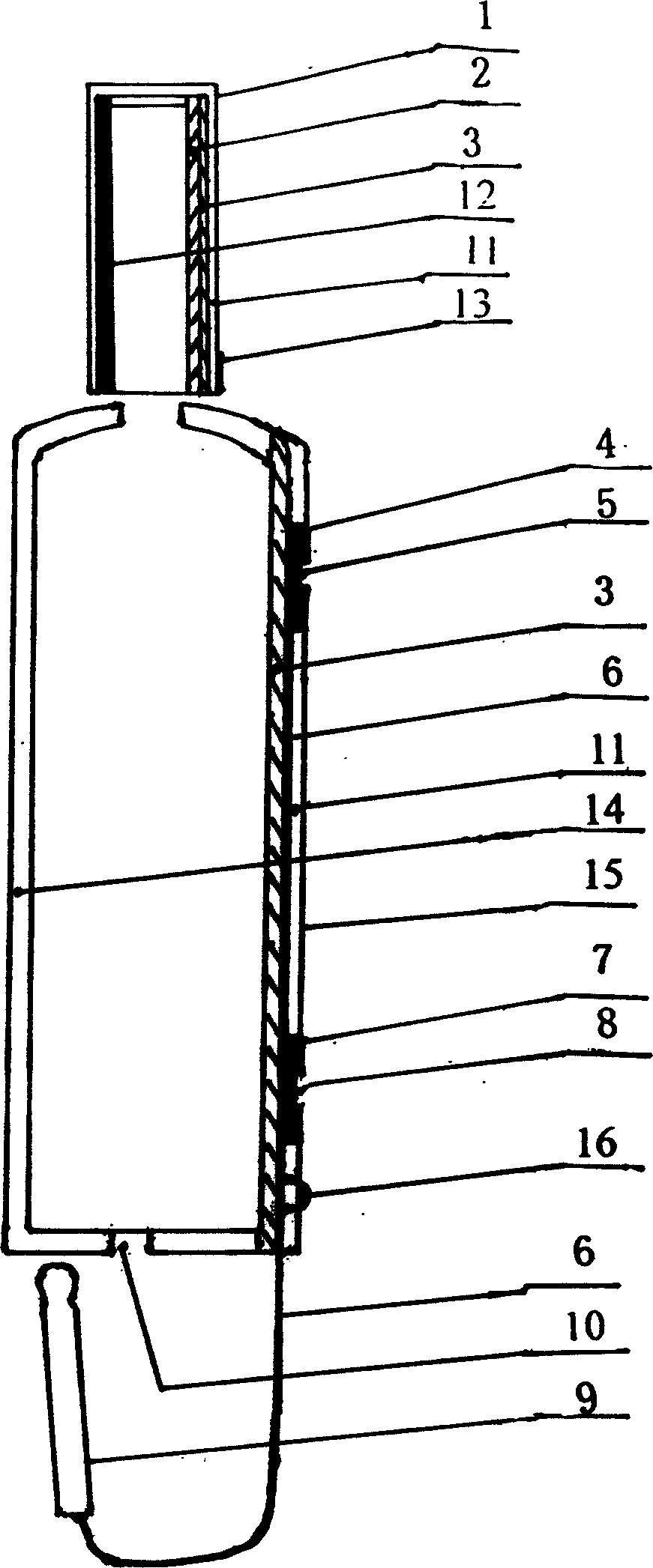
[0016] Embodiment 1: see figure 1 , casting the rubber with ferrite in the mold into a semicircular antenna cap that absorbs electromagnetic waves (2), and another semicircular antenna cap that is cast from rubber material, that is, a rubber material layer (12) Hot pressing or bonding together to make the antenna cap (1), coating an aluminum powder layer on the outer surface of the ferrite semi-arc surface of the antenna cap (1), that is, the reflective electromagnetic wave shielding layer (3) , making an antenna cap (1) with a composite electromagnetic wave shielding layer, and setting a direction mark (13).

[0017] The reflective electromagnetic wave shielding material, such as copper mesh, is heat-pressed and encapsulated in the plastic sheet to make the plastic sheet of the reflective electromagnetic wave shielding layer (3), and the transparent plastic layer (14) is cut and heat-bonded respectively to form a mobile phone case (15); The receiver (4) of the patch cord ear...

Embodiment 2

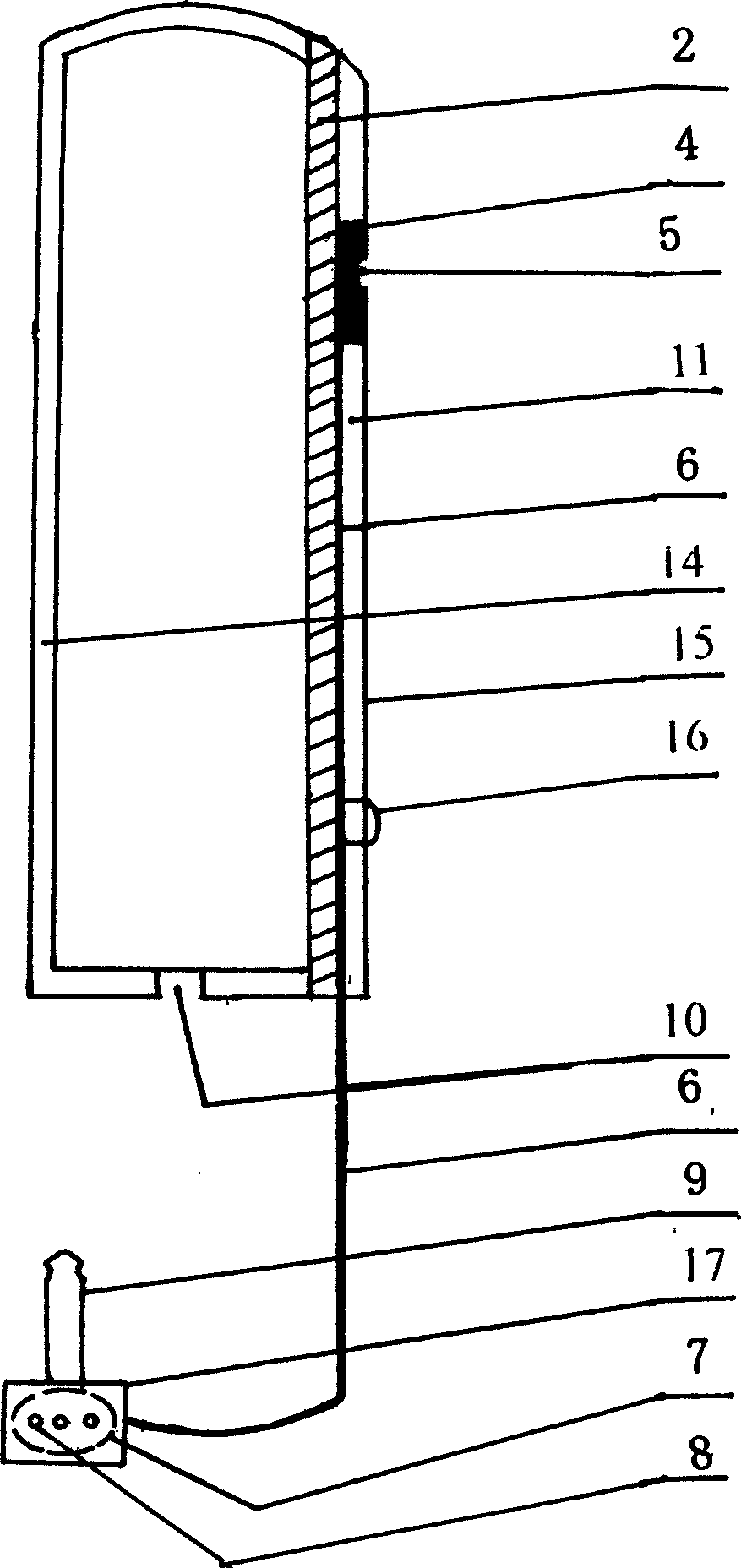
[0019] Example 2: see figure 2 , the plastic material with ferrite is made into a plastic sheet that absorbs the electromagnetic wave shielding layer (2), and the transparent plastic layer (14) is cut and heat-bonded respectively to make a mobile phone cover (15); (4) be arranged on the outer upper part of the mobile phone case (15) that absorbs the electromagnetic wave shielding layer (2), and use a transparent plastic sheet as the protective layer (11) to heat seal the mobile phone case (15) on the side that has the electromagnetic wave shielding layer (2) ), leave part of the signal connection line (6) and the power plug (9), wrap and fix the receiver (4), another part of the signal connection line (6), and the microphone (7) in the mobile phone case (15 ) and the protective layer (11), there is a receiver hole (5) on the outer side of the receiver, and a microphone protective cover (17) is welded or bonded to the exposed part after the power plug is inserted into the jack...


PUM


Abstract

A back-hearing type anti-radiation handset jacket includes an antenna cap, a handset jacket, a phone receiver, a phone transmitter a signal connecting wire and a power supply plug characterized by that a magnetic wave shielding layer is set up at one side of the antenna cap the transmitter and part signal line and / or shield layer are enclosed fixedly between the jacket and the protection layer, the plug and part signal lines are left outside the outder side of thej acket, and the side shielding is made of transparent material. In using, the view window and the key board are towards the transparent side and the side with the shielding layer is towards the body.

Description

Technical field: [0001] The invention relates to the technical field of electromagnetic compatibility, in particular to a listening-back type anti-radiation mobile phone cover. Background technique: [0002] Mobile phone handsets are referred to as mobile phones, which emit electromagnetic waves in all directions during calls. Excessive or long-term electromagnetic radiation will affect the health of users. The usual mobile phone is to install the receiver, display, keyboard, and microphone on the mobile phone. Close to the inner side of the human body, when the user is talking, the receiver hole of the inner casing must be attached to the ear for two-way communication. At the same time, electromagnetic waves continuously radiate the user's head through the antenna and the inner casing. brain parts, thereby causing harm to the health of users. [0003] At present, the use of plug-in earphones is one of the effective ways to reduce the damage of electromagnetic radiation to ...

Claims


Application Information

Patent Timeline
Patent Type & Authority Applications(China)
IPC IPC(8): H04M1/02H05K9/00
Inventor 朱炜
Owner 朱炜
Learn More