Quick configuration method for LTE (Long Term Evolution) SRS (Sounding Reference Signal) frequency domain position

A technology for rapid configuration and detection of signals, applied in wireless communication, electrical components, etc., can solve problems such as uplink scheduling gain loss

Active Publication Date: 2014-04-02
NANJING PANDA ELECTRONICS +2
View PDF2 Cites 3 Cited by
  • Summary
  • Abstract
  • Description
  • Claims
  • Application Information

AI Technical Summary

Problems solved by technology

Therefore, the disadvantages of performing SRS frequency hopping according to the method proposed in the existing TS36.211 p

Method used


Image

  • Quick configuration method for LTE (Long Term Evolution) SRS (Sounding Reference Signal) frequency domain position
  • Quick configuration method for LTE (Long Term Evolution) SRS (Sounding Reference Signal) frequency domain position
  • Quick configuration method for LTE (Long Term Evolution) SRS (Sounding Reference Signal) frequency domain position

Examples


Embodiment Construction

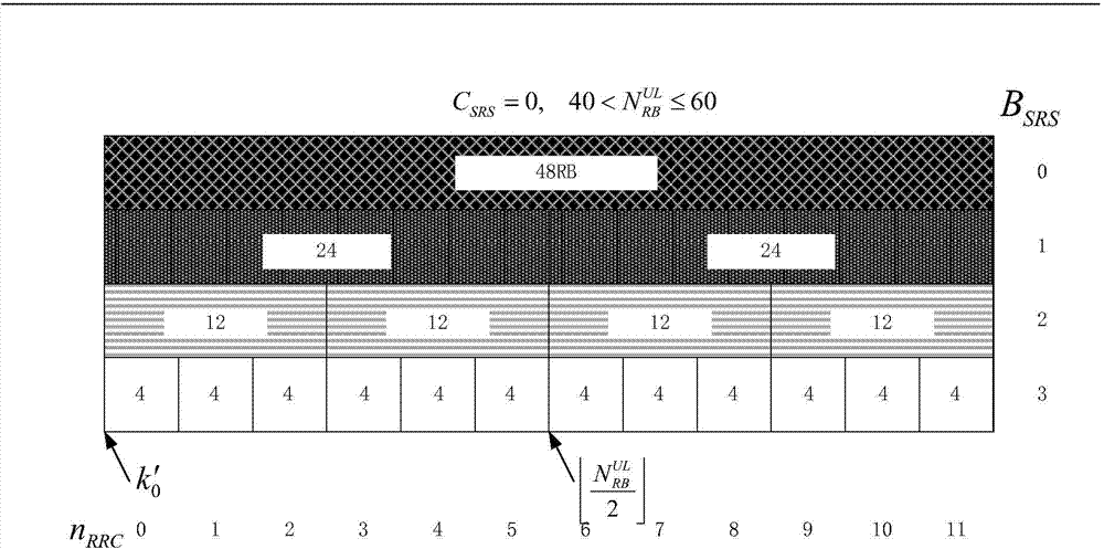
[0113] Due to the simplicity of the channel detection method in the fixed frequency band, here only for the frequency hopping mode, the figure 1 The configuration is taken as an example, and three different parameter settings are respectively considered to illustrate the implementation method of the present invention under different situations.

[0114] First, suppose C SRS =1,b hop = 0, B SRS =3. Assume 4n RRC =40, get n=10, according to sub-flow A, u → = { 0,1 , · · · , 11 } . thereby,

[0115] M 0 = 0 1 2 3 4 5 ...


PUM


Abstract

The invention relates to a quick configuration method for an LTE (Long Term Evolution) SRS (Sounding Reference Signal) frequency domain position. Fixed frequency band channel sounding can prove a situation as shown by the accompanying drawing during uplink channel sounding at a fixed frequency domain position and a situation that channel sounding through a frequency hopping method is performed through a subprogram A, a subprogram B and a subprogram C. The invention provides a simplified algorithm and the calculation of n1, n2 and n3 is avoided; in the frequency hopping method, the algorithm can also improve the hop frequency of UE (User Equipment) channel sounding and can bring about uplink scheduling gains.

Description

technical field [0001] The invention relates to the configuration of the detection signal of the LTE communication system in mobile communication, in particular to the rapid configuration method for the frequency domain position of the uplink detection signal. Background technique [0002] In an LTE communication system, a terminal device (UE) needs to periodically send an uplink sounding signal (SRS) to assist a base station (enodeB) in frequency selective scheduling in the uplink direction. Before channel detection, the UE needs to determine the starting position in the frequency domain and the detection bandwidth for sending the SRS. These parameters are given by enodeB. The detection bandwidth may be the entire uplink system bandwidth or a part of the uplink bandwidth. When the UE is at the edge of the cell, it usually needs to perform multiple detections to complete a detection process with a specified uplink bandwidth. At this time, the starting position of the frequ...

Claims


Application Information

Patent Timeline
IPC IPC(8): H04W24/00
Inventor 曾炜
Owner NANJING PANDA ELECTRONICS
Why Eureka
Try Eureka