Slider for slide fastener

A technology for sliders and zippers, applied in the field of sliders for zippers, can solve the problems of small size and reduced necessary strength of sliders, and achieve the effect of ensuring strength

Inactive Publication Date: 2014-04-02
YKK CORP
View PDF5 Cites 5 Cited by
  • Summary
  • Abstract
  • Description
  • Claims
  • Application Information

AI Technical Summary

Problems solved by technology

[0005] However, with the downsizing of zippers in recent years, it is also necessary to downsize the slider, so the dimensions of the slider in the width direction, up-down direction (thickness direction), and front-back direction have to be designed to be small.
However, in the slide fastener slider described in Patent Document 1, since the rear mounting column, the claw hole, the guide surface, the protrusion, and the front mounting portion are formed along the front-rear direction of the slider, if each of the sliders is simply reduced, size, there is a possibility that the necessary strength of the slider will be reduced

Method used


Image

  • Slider for slide fastener
  • Slider for slide fastener
  • Slider for slide fastener

Examples


Embodiment Construction

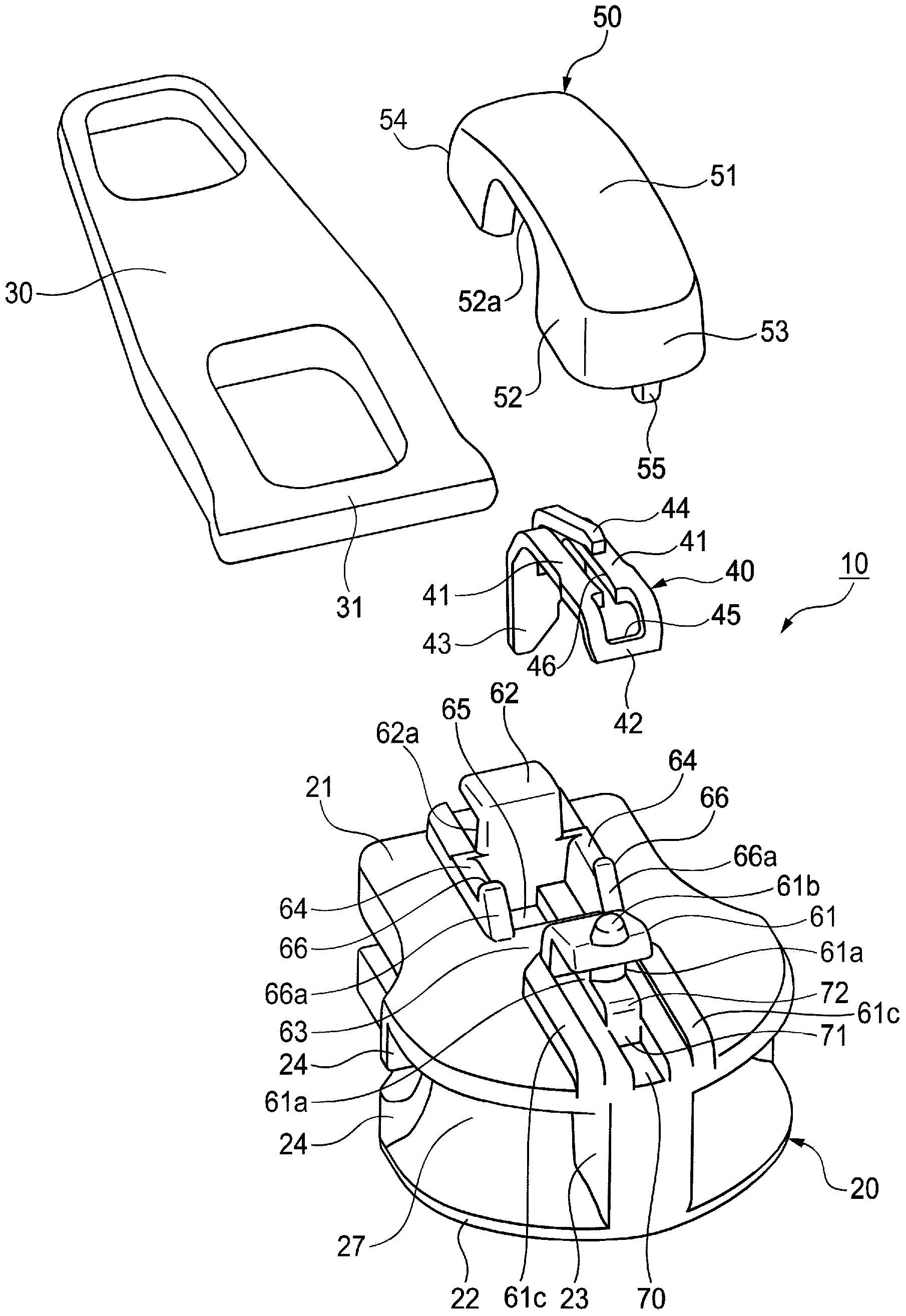
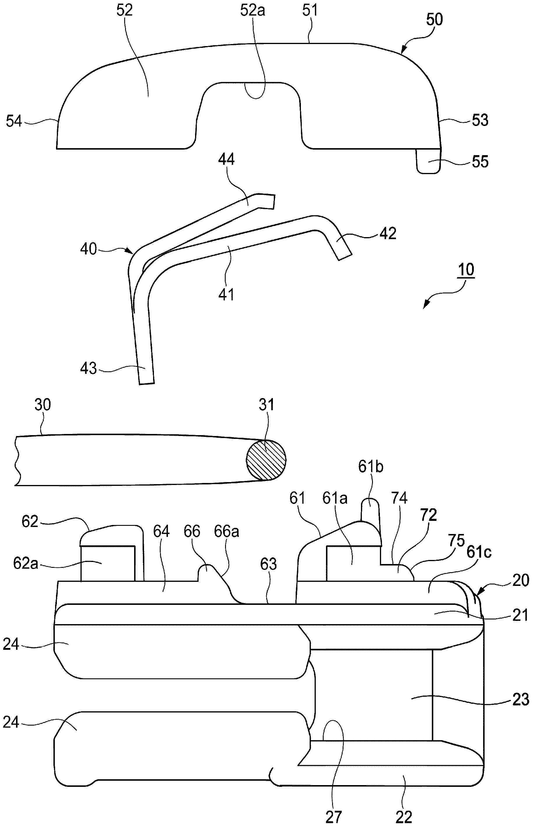
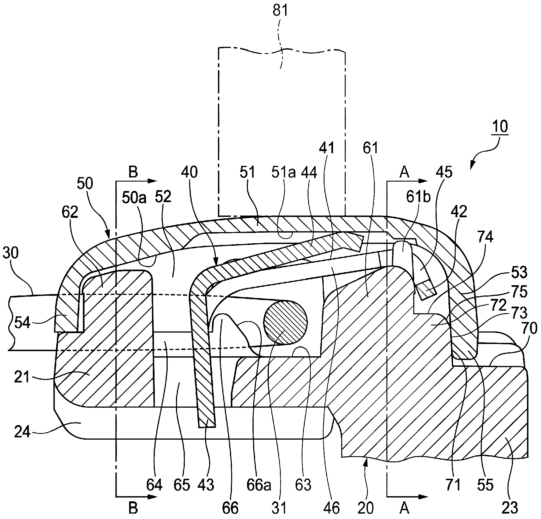
[0022] Hereinafter, one Embodiment of the slider for slide fasteners which concerns on this invention is demonstrated in detail based on drawing. In addition, in the description mentioned later, let the side which is the side where the slider width is wide and the fastener elements come out separated as a shoulder opening side, and let the side which is the side where the slider width is narrow and the fastener elements come out meshed be the shoulder opening side. Posterior side. In addition, the shoulder side is defined as the front, the rear mouth side is defined as the rear, the sliding direction of the slider is defined as the front-rear direction, and the direction perpendicular to the front-rear direction and parallel to the fastener tape (not shown) is defined as the left-right direction (width direction). The direction perpendicular to the front-rear direction and the left-right direction is the up-down direction.

[0023] Such as Figure 1 ~ Figure 3 As shown, the ...


PUM


Abstract

Provided is a slider for a slide fastener in which the size of the slider is reduced, sufficient slider strength is obtained, and a cover body can be positioned on a slider body in a reliable manner. The slider body (20) has a groove (70) formed on an upper blade plate (21) further towards the shoulder side than a front mounting column (61). A stopping claw body (40) has a latching section (42) which is latched to the upper end of the front mounting column (61). The cover body (50) has a projection (55) protrudingly provided on the lower end surface of a front plate (53), the projection fitting into the groove (70). A shaft (31) of a pull (30) is installed between the upper blade plate (21) and the stopping claw body (40). The cover body (50) is fixed to the slider body (20) in a state in which the latching section (42) is latched to the upper end of the front mounting column (61), a stopping claw (43) of the stopping claw body (40) is inserted into a claw hole (65) of the upper blade plate (21), and the front mounting column (61) and a rear mounting column (62) are housed in the cover body (50). The groove (70) has a groove end surface (71) positioned further forward relative to the tip of the latching section (42) in a state of being latched to the upper end of the front mounting column (61).

Description

technical field [0001] The present invention relates to a slider for slide fasteners. Background technique [0002] As a conventional slide fastener slider, there is known a slider having a structure in which a stop claw is placed on an upper portion of a front mounting column of the slider main body, and a cover is covered from above the stop claw. This type of slider is used to position the cover and press the cover in the front-back direction by making the rear mounting post and protrusion, or the guide surface and the protrusion contact each part of the corresponding cover. (For example, refer to Patent Document 1) [0003] prior art literature [0004] Patent Document 1: Japanese Patent Application Laid-Open No. 10-127313 [0005] However, since the size of the slide fastener has been downsized in recent years, the size of the slider has also been required, so the width direction, the up-down direction (thickness direction), and the dimension of the front-rear direct...

Claims


Application Information

Patent Timeline
Patent Type & Authority Applications(China)
IPC IPC(8): A44B19/30
CPCA44B19/306
Inventor 埴生雅裕宫崎阳平小泽贵敬槻庆一
Owner YKK CORP
Why Eureka
Try Eureka