
Automatic turnover mechanism

An automatic flipping and horizontal moving technology, applied in rotary conveyors, conveyors, metal processing, etc., can solve the problems of the appearance quality of the workpiece to be processed, the impact of processing accuracy, and inaccurate positioning, so as to improve the stability of clamping , high turnover efficiency, and the effect of improving production efficiency

Inactive Publication Date: 2014-04-09
SANKYO PRECISION HUIZHOU
View PDF7 Cites 15 Cited by
  • Summary
  • Abstract
  • Description
  • Claims
  • Application Information

AI Technical Summary

Problems solved by technology

However, during the turning process of the manipulator, the center will shift, so that the center of gravity of the irregularly shaped workpiece to be processed will change after being rotated, causing it to enter the next process due to inaccurate positioning and the processing accuracy will be affected.
In addition, in order to ensure that the workpiece to be processed is not easy to fall off, the manipulator needs to be in contact with the OEM workpiece in a large area and exert a certain clamping force, which will affect the appearance quality of the workpiece to be processed

Method used


Image

  • Automatic turnover mechanism
  • Automatic turnover mechanism

Examples


Embodiment Construction

[0020] The present invention will be further described in detail below with reference to the embodiments and the accompanying drawings, but the embodiments of the present invention are not limited thereto.

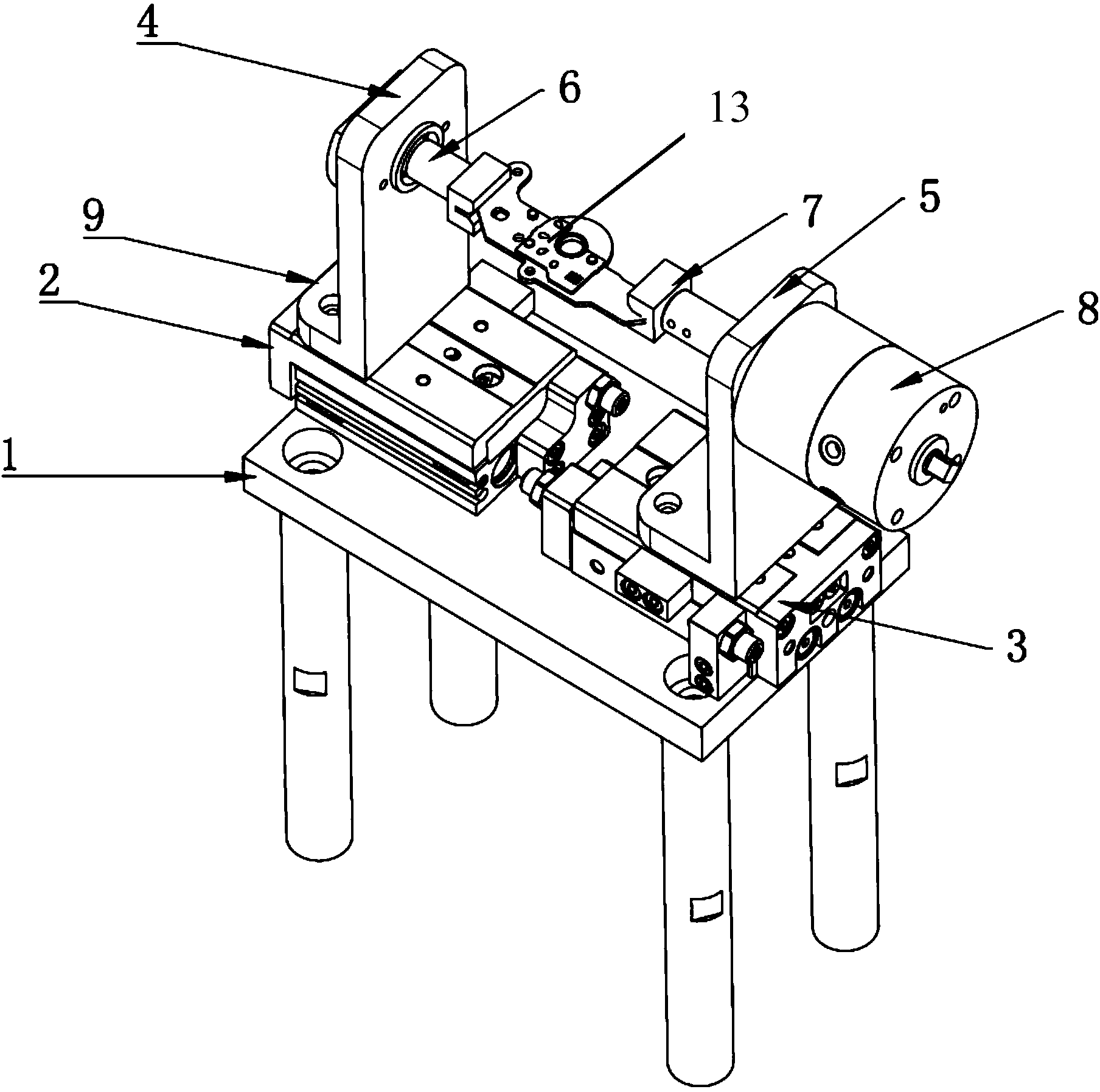
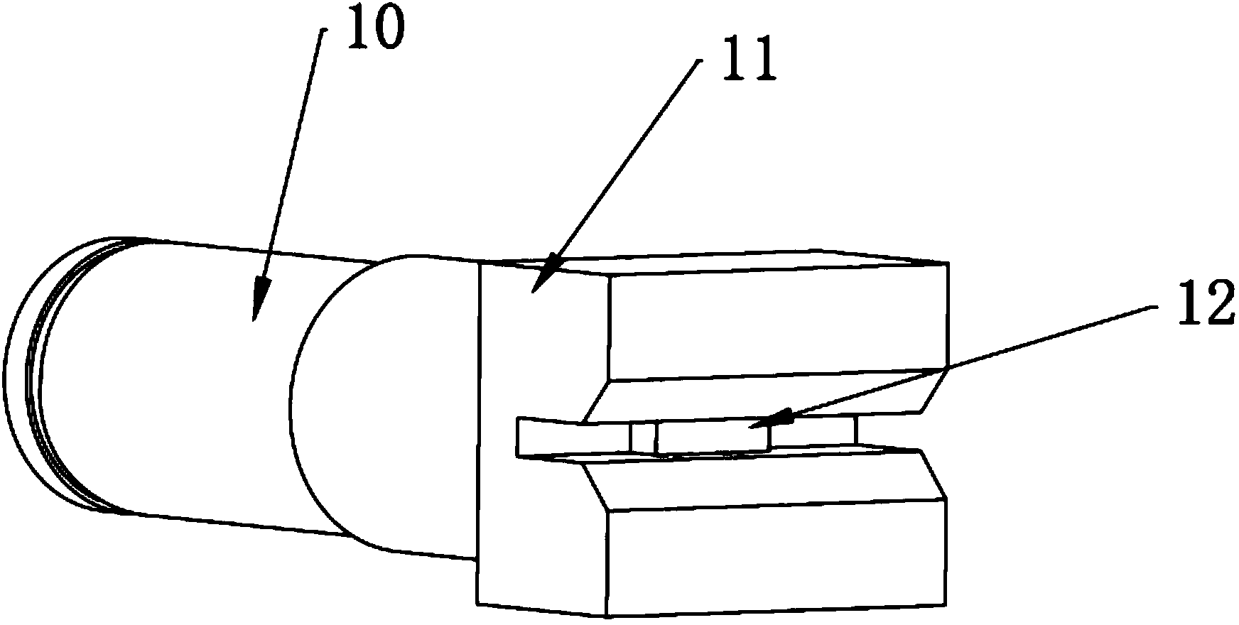
[0021] Such as figure 1 As shown, an automatic turning mechanism includes a base 1, a clamping device composed of a left clamping block 2 and a right clamping block 3, and a workpiece clamping device composed of a left clamping shaft 6 and a right clamping shaft 7 device. The support frame 4 is fixed on the left top tight block 2, and the support frame 5 is fixed on the right top tight block 3, wherein the support frame 4 and the support frame 5 are L-shaped, and the horizontal plane 9 in the support frame 4 is fixed on the left top tight block by screws. On the block 2, the horizontal plane in the support frame 5 is fixed on the right tight block 3 by screws.

[0022] The support frame 4 and the support frame 5 are respectively provided with bushing holes, one end of th...


PUM


Abstract

The invention discloses an automatic turnover mechanism. The automatic turnover mechanism comprises a base, an ejecting device and a device for clamping workpieces to be machined. The ejecting device is composed of a left ejecting block and a right ejecting block, wherein the left ejecting block and the right ejecting block can horizontally move. Supporting frames are fixed to the left ejecting block and the right ejecting block respectively, and shaft sleeve holes are formed in the supporting frames. The device for clamping the workpieces to be machined comprises a left clamping shaft and a right clamping shaft, one end of the left clamping shaft penetrates through the shaft sleeve hole in the corresponding supporting frame and can horizontally move along with the supporting frame, one end of the right clamping shaft penetrates through the shaft sleeve hole in the corresponding supporting frame and then is connected with a rotating air cylinder, and the right clamping shaft can rotate along with the rotating air cylinder and horizontally move along with the corresponding supporting frame. The rotating axis of the device for clamping the workpieces to be machined is fixed creatively, it is guaranteed that the gravity of the workpieces to be machined does not change after the workpieces to be machined are rotated, and therefore machining accuracy is improved. The automatic turnover mechanism can be turned over at any angle, and turnover efficiency is high. The appearance quality of the workpieces to be machined cannot be affected in the turnover process.

Description

technical field [0001] The invention relates to the technical field of automation equipment, in particular to an automatic turning mechanism, in particular to an automatic turning mechanism designed for asymmetrical materials. Background technique [0002] At present, after the processing of one side of the product is completed, it is often necessary to rotate it so that the processing equipment can process the other surface. In the prior art, the workpiece to be processed is often turned over manually. This method of operation requires special personnel to be arranged at the workstation, which increases the cost input. Moreover, manual flipping also greatly reduces production efficiency. Furthermore, manual flipping also has poor stability and risks of missing flips. [0003] With the development of industrial automation level, those skilled in the art try to realize the turning of the material to be processed by means of automatic turning equipment. For example, the Ch...

Claims


Application Information

Patent Timeline
Patent Type & Authority Applications(China)
IPC IPC(8): B23Q7/00
CPCB65G29/00
Inventor 王伟黄妙青邓广易陈兴平蒋宗健
Owner SANKYO PRECISION HUIZHOU
Learn More