Photovoltaic energy storage louvre

A photovoltaic energy storage and shutter technology, applied in photovoltaic modules, photovoltaic power generation, photovoltaic module support structures, etc., can solve the problems of affecting light transmittance, low energy conversion efficiency, temperature exposure, etc. Energy storage efficiency and the effect of increasing the light-receiving area

Active Publication Date: 2019-12-20
牡丹江力同木业有限公司
View PDF6 Cites 5 Cited by
  • Summary
  • Abstract
  • Description
  • Claims
  • Application Information

AI Technical Summary

Problems solved by technology

However, the photovoltaic energy storage shutters in the prior art are the same as ordinary shutters. When the sun is hot, it is still necessary to manually close the shutters to achieve the purpose of shielding the sun and increasing the energy storage efficiency of photovoltaic panels, which is particularly troublesome. When there is no one at home or indoors, the blinds cannot be closed automatically, not only the sunlight will irradiate the indoor temperature extremely high, but also the light-receiving area of ​​the photovoltaic panel is kept at a minimum, and the energy conversion efficiency is very low
[0004] Moreover, during the working process of the photovoltaic panel, although it is protected by a glass cover, dust is easily absorbed on the glass cover, which has a significant impact on the power generation efficiency of the photovoltaic panel.
First, the dust on the surface of the glass cover affects the transmittance of light, which in turn affects the radiation received by the surface of the module; second, the dust will form shadows on the surface of the photovoltaic panel, causing hot spot effects on the local photovoltaic panel, and further affecting Photovoltaic panels cause damage, affecting power generation efficiency and shortening the life of photovoltaic panels

Method used


Image

  • Photovoltaic energy storage louvre
  • Photovoltaic energy storage louvre

Examples


Embodiment Construction

[0018] The technical solutions in the embodiments of the present invention will be clearly and completely described below in conjunction with the accompanying drawings in the embodiments of the present invention. Obviously, the described embodiments are only a part of the embodiments of the present invention, rather than all the embodiments.

[0019] In the description of the present invention, it should be understood that the terms "upper", "lower", "front", "rear", "left", "right", "top", "bottom", "inner", " The orientation or positional relationship indicated by “outside” is based on the orientation or positional relationship shown in the drawings, and is only for the convenience of describing the present invention and simplifying the description, and does not indicate or imply that the device or element referred to must have a specific orientation to The specific azimuth structure and operation cannot be understood as a limitation of the present invention.

[0020] Reference ...


PUM


Abstract

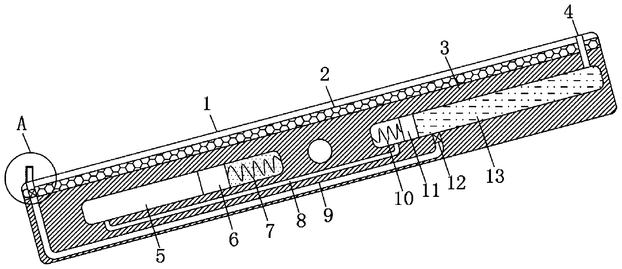
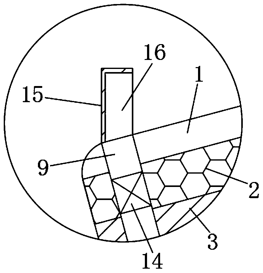
The invention discloses a photovoltaic energy storage louvre. The photovoltaic energy storage louvre comprises a louvre blade and a photovoltaic panel, wherein the photovoltaic panel is installed on the upper end of the louvre blade, the photovoltaic panel is coupled with a storage battery, a glass cover plate covers the upper end of the photovoltaic panel, a first sliding cavity is formed in thelouvre blade and is located below the axis of the louvre blade, and a control mechanism which is used for controlling the angle of inclination of the louvre blade is installed in the first sliding cavity. According to the photovoltaic energy storage louvre, the control mechanism, a cooling mechanism and a backflow mechanism are arranged, so that when the louvre is illuminated by sunlight and the temperature of the louvre rises, the louvre is automatically inclined at a certain angle, the higher the temperature is, the larger the angle of inclination is, the effects of shading from the sun, increasing the illuminating area of the photovoltaic panel and improving the energy storage efficiency of the photovoltaic panel are effectively achieved, when the louvre is inclined, cleaning liquid canbe sprayed so as to remove dust from the glass cover plate, so that the hot spot effect of the photovoltaic panel due to dust is prevented, the generating efficiency and the service life of the photovoltaic panel are guaranteed, and the cleaning liquid can be recycled, so that resources are saved.

Description

Technical field [0001] The invention relates to the technical field of photovoltaic energy storage, in particular to photovoltaic energy storage shutters. Background technique [0002] At present, most of the shutters on the market are used in homes, offices and other occasions, and are generally used for indoor and outdoor shading and ventilation. The general purpose of shutters is mainly to look beautiful and protect indoor privacy. Modern shutters can also use related materials to achieve heat preservation effect to achieve the purpose of warming in winter and cooling in summer, and can also effectively block ultraviolet rays. [0003] Photovoltaic energy storage shutters installed with photovoltaic panel systems can use the shutters as a carrier to directly use solar energy for new energy storage and utilization, which has a huge market and potential. However, the photovoltaic energy storage blinds in the prior art are the same as ordinary blinds. When the sun is blazing, the ...

Claims


Application Information

Patent Timeline
IPC IPC(8): E06B7/084E05F1/00H02S20/32H02S40/10H02S40/42
CPCE05F1/004E06B7/084H02S20/32H02S40/10H02S40/425Y02E10/50
Inventor 朱立立
Owner 牡丹江力同木业有限公司
Why Eureka
Try Eureka