Method for preparing hidden-type emitter silicon solar cells

A silicon solar cell, concealed technology, used in photovoltaic power generation, circuits, electrical components, etc., can solve the problems of reducing the effective light-receiving area of ​​the battery, reducing the output current of the collector, and increasing the series resistance of the emitter, and achieves easy industrial automation. The effect of production, reducing wiring resistance and increasing collector current

Inactive Publication Date: 2010-06-23
YUNNAN NORMAL UNIV
View PDF0 Cites 13 Cited by
  • Summary
  • Abstract
  • Description
  • Claims
  • Application Information

AI Technical Summary

Problems solved by technology

First of all, although the area occupied by the grid electrode is very small, accounting for only 8% of the front area of ​​the battery, it still blocks part of the sunlight, reduces the effective light-receiving area of ​​the battery, reduces the density of the photo-generated current, and is not conducive to improving the efficiency of the solar cell; secondly , since the positive and negative electrodes are on both sides of the battery respectively, it needs to be welded from the front of one battery to the back of the other battery with tin-coated tape. Since the path of the emitter current is very long, the series resistance of the emitter increases, reducing the collector output current; secondly, when the components are packaged, the double-sided connection of the emitter makes the automatic production more difficult

Method used


Image

  • Method for preparing hidden-type emitter silicon solar cells

Examples


Embodiment Construction

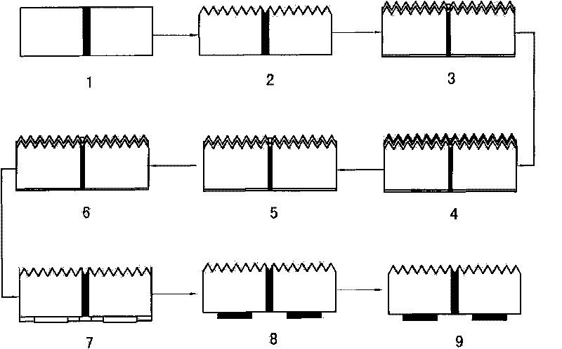
[0033] 1. Laser drilling on a 125mm×125mm p-type silicon wafer with a hole density of 0.5hole / mm 2 .

[0034] 2. Cleaning, polishing, removing radiation damage and texturing of silicon wafers.

[0035] Use the following steps to clean and remove impurities on the silicon wafer:

[0036] 1) Wash the surface of the silicon wafer several times with deionized water to remove large impurity particles on the surface of the silicon wafer.

[0037] 2) Ultrasonic cleaning several times with detergent, and then rinse several times with a large amount of hot and cold deionized water to remove the grease on the surface of the silicon wafer.

[0038] 3) Boil the silicon wafer with concentrated sulfuric acid until white smoke is emitted to remove pollutants on the surface of the silicon wafer.

[0039] The corrosion time of the texturizing corrosive solution is 30 minutes. After the texturing is finished, rinse several times alternately with a large amount of hot and cold deionized water...


PUM


Abstract

The invention relates to a method for preparing hidden-type emitter silicon solar cells, which adopts a quadratic diffusion process. The method comprises the following steps: 1. laser boring; 2. cleaning, radiation damage removing and suede preparation; 3. diffusion; 4. hiding launching area; 5. emitter area corrosion and periphery joint removing; 6. hiding removing; 7. oxidizing and surface passivation; 8. screen printing electrode; and 9. sintering. The method can prepare the hidden-type emitter silicon solar cells.

Description

technical field [0001] The invention belongs to a method for manufacturing a silicon solar cell. Background technique [0002] In the current general silicon solar cell design and manufacturing method, the emitter and emitter electrodes are located on the front of the cell, and this structure has limitations. First of all, although the area occupied by the grid electrode is very small, accounting for only 8% of the front area of ​​the battery, it still blocks part of the sunlight, reduces the effective light-receiving area of ​​the battery, reduces the density of the photo-generated current, and is not conducive to improving the efficiency of the solar cell; secondly , since the positive and negative electrodes are on both sides of the battery respectively, it needs to be welded from the front of one battery to the back of the other battery with tin-coated tape. Since the path of the emitter current is very long, the series resistance of the emitter increases, reducing the c...

Claims


Application Information

Patent Timeline
Patent Type & Authority Applications(China)
IPC IPC(8): H01L31/18H01L31/042
CPCY02E10/52Y02P70/50
Inventor 龙维绪涂洁磊廖华刘祖明李景天申兰先马逊赵恒利杨培志
Owner YUNNAN NORMAL UNIV
Why Eureka
Try Eureka