Dial-drawing device and dial-drawing method for trough-type indicating instrument

A technology of indicating instruments and drawing boards, which is applied in the field of substation indicating instruments reforming devices, can solve the problems of low work efficiency, inability to guarantee measurement accuracy, time-consuming and labor-intensive problems, and achieve the effects of automatic control, improved drawing efficiency, and reasonable layout

Active Publication Date: 2015-04-22
STATE GRID CORP OF CHINA +1
View PDF7 Cites 0 Cited by
  • Summary
  • Abstract
  • Description
  • Claims
  • Application Information

AI Technical Summary

Problems solved by technology

[0002] During the long-term working process of the substation indicating instrument, with the replacement of the primary side current transformer, the indicating instrument on the secondary side should also be replaced accordingly. When there is an indicating instrument with the same transformation ratio, it can be directly replaced. When changing the indicator instrument, it is necessary to redraw the dial of the existing indicating instrument with different range and ratio. The instrument dial of the slot-type indicating instrument is arc-shaped, and there is no special tool for drawing scale points when remaking the instrument dial. , can only be operated by experience. Due to the differences in work experience and technical level of each person, the level of craftsmanship of the re-drawn dials is very different. , due to the long period of restructuring, it will even affect the normal and stable operation of the entire power grid

Method used


Image

  • Dial-drawing device and dial-drawing method for trough-type indicating instrument
  • Dial-drawing device and dial-drawing method for trough-type indicating instrument
  • Dial-drawing device and dial-drawing method for trough-type indicating instrument

Examples


Embodiment Construction

[0028] The present invention will be further described in detail below in conjunction with specific embodiments, which are explanations of the present invention rather than limitations.

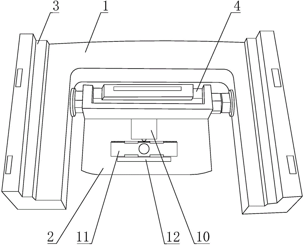
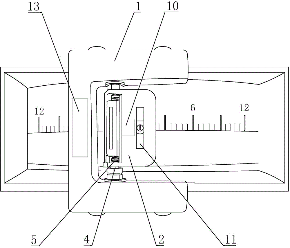
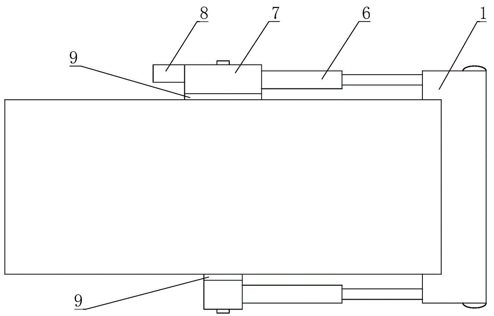
[0029] A trough-shaped indicating instrument drawing board device, comprising a U-shaped sliding frame 1, a drawing positioning system, a telescopic pull rod 6, a fixed suction cup 9, and a drive control system;

[0030] Such as figure 1 As shown, the drawing positioning system includes a drawing platen 2, a drawing motor 10 fixed on the drawing platen 2, a drawing frame 11, and a scanning port 12 arranged on the back side of the drawing platen 2; The rotating shaft 4 provided between the two side arms is connected; the line drawing frame 11 is arranged parallel to the rotating shaft 4, and is slidingly connected with the drawing platen 2, and the middle part of the line drawing frame 11 is fixedly provided with a drawing pen; the drawing motor 10 is connected to the line drawing frame throug...


PUM


Abstract

The invention discloses a dial-drawing device for a trough-type indicating instrument. The dial-drawing device comprises a U-shaped sliding rack, a drawing positioning system, telescopic pull bars, fixed suckers, and a drive control system. The drawing positioning system comprises a drawing press plate, a drawing motor and a line drawing rack which are fixed on the drawing press plate, and a scanning port arranged on the back side of the drawing press plate. The drive control system comprises a rotary motor, an angle sensor, an LED lamp, a CCD image sensor, a photoelectric converting circuit, a single-chip microcomputer, and an input device, wherein the LED lamp and the CCD image sensor are arranged inside the scanning port; and a reception light beam of the CCD image sensor and a drawing pen intersect at the drawing point of the drawing pen. A dial-drawing method described by the invention comprises the following steps of 1) inputting dial drawing parameters; 2) acquiring a start point and a stop point of a measuring range; 3) determining a scale division angle [alpha] being corresponded with a scale division value m and a marking angle [beta] being corresponded with a marking value M; and 4) positioning and starting to draw scale marks under the control of the single-chip microcomputer from the start point.

Description

technical field [0001] The invention relates to a device and method for remanufacturing a substation indicating instrument, in particular to a device and a method for drawing a panel of a slot-type indicating instrument. Background technique [0002] During the long-term working process of the substation indicating instrument, with the replacement of the primary side current transformer, the indicating instrument on the secondary side should also be replaced accordingly. When there is an indicating instrument with the same transformation ratio, it can be directly replaced. When changing the indicator instrument, it is necessary to redraw the dial of the existing indicating instrument with different range and ratio. The instrument dial of the slot-type indicating instrument is arc-shaped, and there is no special tool for drawing scale points when remaking the instrument dial. , can only be operated by experience. Due to the differences in work experience and technical level o...

Claims


Application Information

Patent Timeline
Patent Type & Authority Patents(China)
IPC IPC(8): B41J3/00G01B11/26
Inventor 李战荣孟菊郭雯郭麦婵戴敏周立忠
Owner STATE GRID CORP OF CHINA
Why Eureka
Try Eureka