
Printer and printer head driving method

A driving method and technology of a print head, applied in the directions of printing devices, printing, etc.

Inactive Publication Date: 2014-04-09
OKI DATA CORP
View PDF7 Cites 4 Cited by
  • Summary
  • Abstract
  • Description
  • Claims
  • Application Information

AI Technical Summary

Problems solved by technology

[0015] The object of the present invention is to solve the problems of the existing printers, and provide a printer and a printer capable of printing with appropriate print quality and appropriate print speed according to the operator's requirements for the type of print data and the form of media, etc. Print head drive method

Method used


Image

  • Printer and printer head driving method
  • Printer and printer head driving method
  • Printer and printer head driving method

Examples


Embodiment Construction

[0036] Hereinafter, embodiments of the present invention will be described in detail with reference to the drawings. In this case, a printer as a printing device will be described.

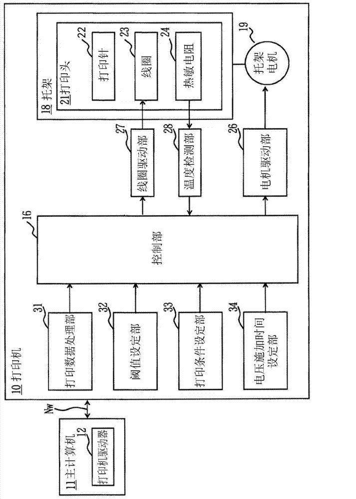
[0037] figure 1 It is a control block diagram of the printing system in the first embodiment of the present invention.

[0038] In the figure, 10 is a printer, 11 is a host computer as a high-level device, Nw is a network that connects the printer 10 and the host computer 11 to form a printing system, and the host computer 11 has a printer driver as a printer operation processing unit for operating the printer 10. 12. Print data is sent from the host computer 11 to the printer 10 via the network Nw, and status information indicating the status of the printer 10 is sent from the printer 10 to the host computer 11 .

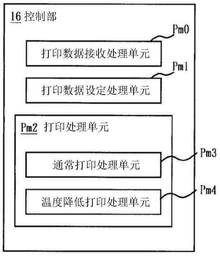
[0039] In addition, 16 is a control unit for performing overall control of the printer 10, 18 is a carriage disposed in the printer 10 so as to be movable in the scanning direction,...


PUM


Abstract

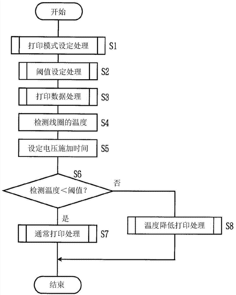
The invention discloses a printer and a printer head driving method. Based on operator's requirement, printing with appropriate quality and speed can be done. The printer comprises a printer head (21), a coil driving part (27), a temperature detection part (28) for detecting the temperature inside the printer head (21), a threshold setting part (32) for controlling the threshold of the temperature inside the printer head (21) by setting corresponding to a printing mode; and a printing condition setting part (33) for setting the printing condition for lowering temperature inside the printer head (21) when the detection temperature is set above the set threshold. When setting the threshold, the printing quality won't be reduced without reducing printing density. When setting the threshold, the printing speed won't be lowered.

Description

technical field [0001] The present invention relates to a printer and a print head driving method. Background technique [0002] In the past, image forming devices such as printers, copiers, facsimile machines, and compound machines, such as dot matrix printers, have print heads, and the printing needles arranged on the print heads are selectively advanced to hit the ink ribbon, and the ink of the ink ribbon is transferred to the ink ribbon. Printing is performed by printing onto paper as a medium. [0003] Therefore, the same number of iron cores as the number of printing pins are arranged on the printing head, and corresponding to each of the iron cores, an armature with the printing needles attached to the front end is swingably arranged. Then, a driving current is supplied to the coils by applying a predetermined voltage to the coils arranged around each iron core, and when the iron cores generate electromagnetic force, the armature is attracted by the iron cores to adv...

Claims


Application Information

Patent Timeline
Patent Type & Authority Applications(China)
IPC IPC(8): B41J29/38
Inventor 佐藤直也
Owner OKI DATA CORP
Learn More