Special trolley for friction conveying in automobile body painting workshop

A car body and painting technology, applied in the direction of conveyors, transportation and packaging, etc., can solve problems such as line stoppage, friction wheel slippage, chain sticking, etc., to reduce friction line stoppage accidents, ensure painting quality, balance strong effect

Active Publication Date: 2015-10-28
武汉东研智慧设计研究院有限公司
View PDF6 Cites 0 Cited by
  • Summary
  • Abstract
  • Description
  • Claims
  • Application Information

AI Technical Summary

Problems solved by technology

[0002] In the conveying system of the body painting workshop, the painting process chain of the painting workshop often uses the lower chain push rod to mesh with the push head at the bottom of the trolley to drive the trolley to run. The installation height of the conveyor in the paint spraying room directly leads to the bottom of the conveyor being closer to the paint spray tank, which brings difficulties to the design of the paint spray tank. At the same time, the water mist and paint mist in the paint spray room also accelerate the corrosion of chains and tracks; There are many turning curves in the friction conveying system, and the line stop phenomenon caused by the slipping of conveying trolleys and trucks is very likely to occur at the curves; in the manual work or robot work area of ​​the painting workshop, it has a negative impact on the stability of the car body. Higher requirements to ensure the process quality of the car body; the middle support of the conveying trolley in the body painting workshop is in the form of an upright column, and it is in the middle of the track. Since the friction beam at the bottom of the track and the trolley is in the middle, even if the protective cover is used Protection, in the painting, grinding and other work stations, it is also very easy to cause contamination of the rails, chains, and friction beams, resulting in chain sticking and friction wheel slipping.

Method used


Image

  • Special trolley for friction conveying in automobile body painting workshop
  • Special trolley for friction conveying in automobile body painting workshop
  • Special trolley for friction conveying in automobile body painting workshop

Examples


Embodiment Construction

[0026] The present invention will be further described in detail below in conjunction with the accompanying drawings and specific embodiments.

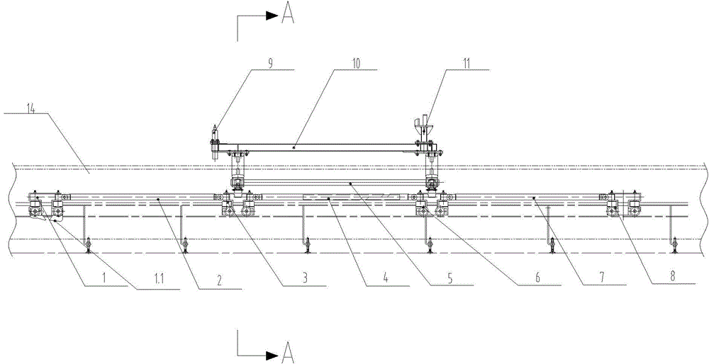
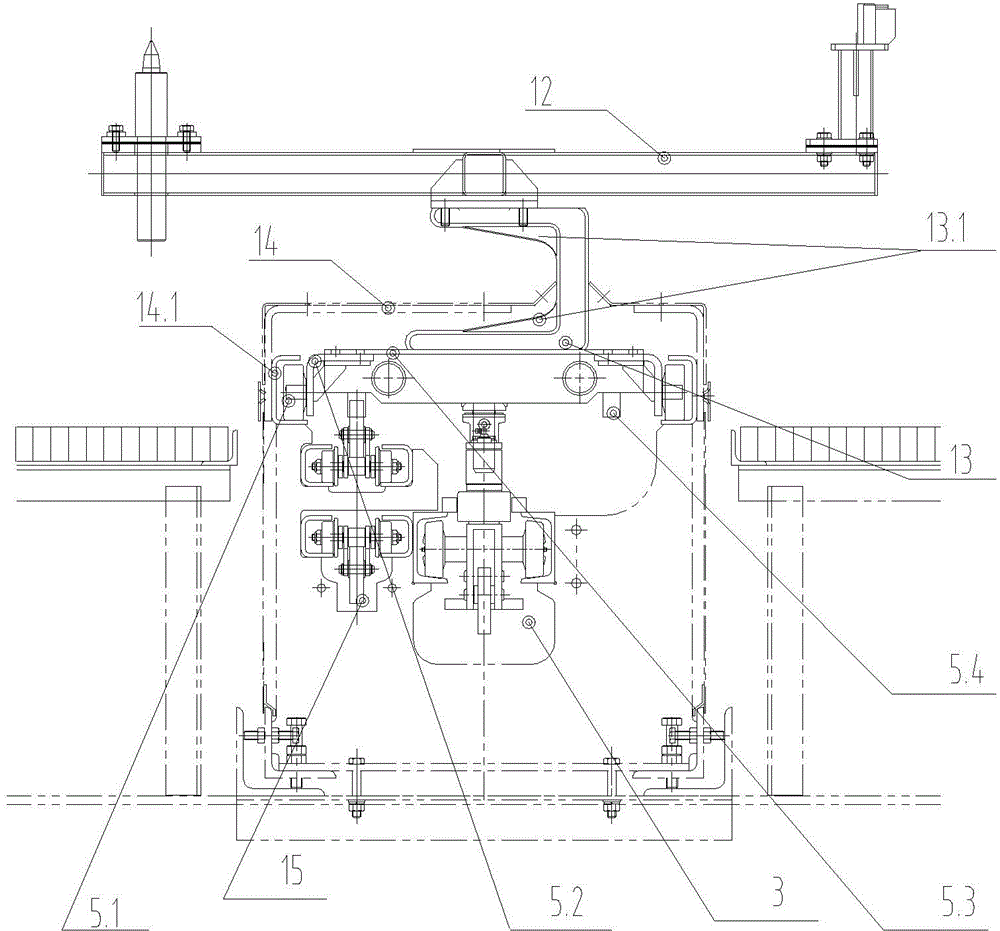
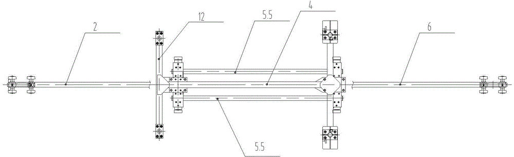
[0027] Such as figure 1 , figure 2 and image 3 Shown is a special trolley for friction conveying in an automobile body painting workshop, which includes segmented friction equalization beams, specifically front friction equalization beam 2, middle friction equalization beam 4, rear friction equalization beam 7, front friction equalization beam 2 One end of the front friction equalization beam 2 is hinged with the first traveling trolley 1, the other end of the front friction equalization beam 2 is hinged with the second traveling trolley 3, one end of the middle friction equalization beam 4 is hinged with the second traveling trolley 3, and the other end of the middle friction equalization beam 4 is hinged with the The third traveling trolley 6 is hinged, one end of the rear friction equalization beam 7 is hinged with the third tr...


PUM


Abstract

The invention discloses a pallet special for friction conveying in an automobile body coating workshop. The pallet comprises walking trolleys, friction balancing beams and a balancing frame. The walking trolleys, the friction balancing beams and the balancing frame are arranged in a protective cover, and two C-type supports are symmetrically arranged at the top of the balancing frame and penetrate through the top of the protective cover. A fixed supporting beam is arranged at the tops of the C-type supports. Openings are formed in the top of the protective cover and used for the C-type supports to penetrate through. The openings are formed in the positions deviating from the vertical center line of the protective cover, so that the trafficability of the pallet is guaranteed, and besides it is effectively avoided that contaminants such as coating mist and sealant enter the protective cover and then directly fall on conveying equipment such as track chains or the balancing beams. The pallet is light, ingenuous in appearance, reasonable in structure, high in balancing performance and capable of being adaptive to special environmental requirements of the automobile body coating workshop, effectively reducing the line stop accidents of a friction line in the coating workshop and improving production quality of stations of paint spraying, gluing, polishing and others.

Description

technical field [0001] The invention relates to the field of mechanized conveying in a car body painting workshop, in particular to a special trolley for friction conveying in a car body painting workshop. Background technique [0002] In the conveying system of the body painting workshop, the painting process chain of the painting workshop often uses the lower chain push rod to mesh with the push head at the bottom of the trolley to drive the trolley to run. The installation height of the conveyor in the paint spraying room directly leads to the bottom of the conveyor being closer to the paint spray tank, which brings difficulties to the design of the paint spray tank. At the same time, the water mist and paint mist in the paint spray room also accelerate the corrosion of chains and tracks; There are many turning curves in the friction conveying system, and the line stop phenomenon caused by the slipping of conveying trolleys and trucks is very likely to occur at the curves...

Claims


Application Information

Patent Timeline
Patent Type & Authority Patents(China)
IPC IPC(8): B65G17/12B65G21/20B65G21/08
Inventor 吕晶夏淼赵华杨江伟刘亚丽
Owner 武汉东研智慧设计研究院有限公司
Why Eureka
Try Eureka