
Electronic control bilateral overrun clutch

An overrunning clutch, electronic control technology, applied in clutches, fluid clutches, mechanical equipment, etc., can solve the problems of low transmission accuracy, complex structure, no reverse gear, etc., to change the traditional thinking, simple and compact structure, and responsive. Effect

Active Publication Date: 2014-04-09
重庆宣叙机械设备有限公司
View PDF8 Cites 0 Cited by
  • Summary
  • Abstract
  • Description
  • Claims
  • Application Information

AI Technical Summary

Problems solved by technology

[0003] In the prior art, most of the overrunning clutches are clutches that use the meshing of teeth, the meshing of ratchets and pawls, or the wedging action of rollers and wedges to transmit motion or torque in one direction, and generally adopt mechanical automatic meshing or separation. Therefore, There is a short time difference from separation to transmission engagement, so the transmission accuracy is low. For the transmission of some precision instruments, ordinary mechanical overrunning clutches cannot meet the requirements
[0004] Furthermore, for general portable vehicles, the overrunning clutch is used as the gear for transmission, and this type of vehicle generally does not have a reverse gear. When the vehicle is pushed backward by manpower, it cannot be realized due to the engagement of the overrunning clutch with the clutch, and the overrunning must be cut off. The transmission chain of the clutch can only be realized, and the structure is more complicated

Method used


Image

  • Electronic control bilateral overrun clutch
  • Electronic control bilateral overrun clutch
  • Electronic control bilateral overrun clutch

Examples


Embodiment Construction

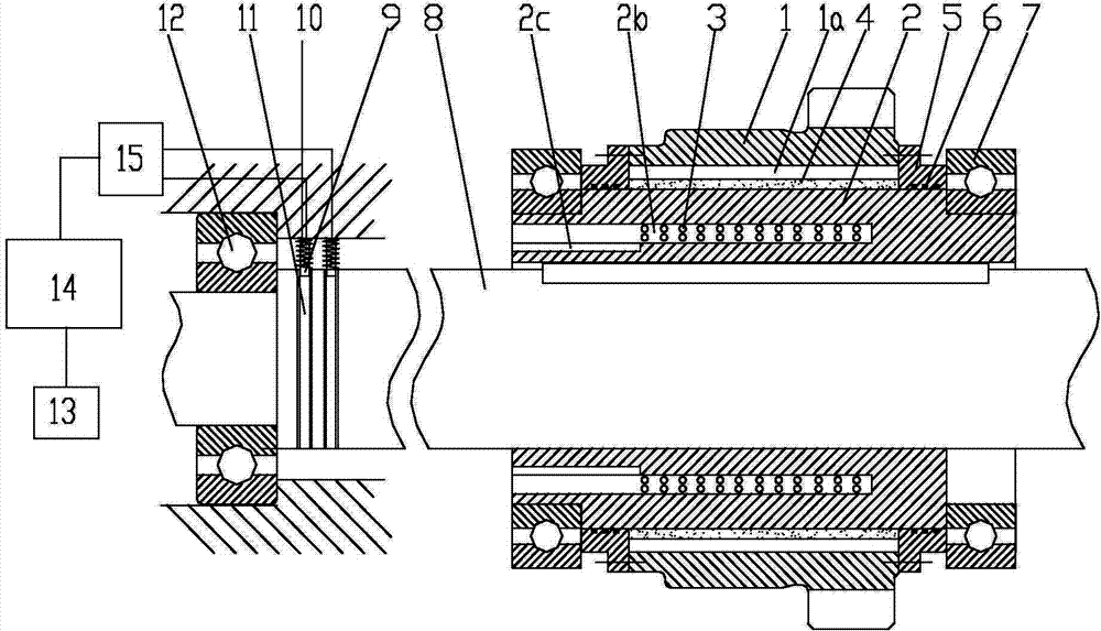
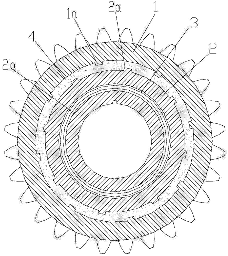
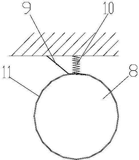
[0022] figure 1 It is a schematic diagram of the structure of the present invention, figure 2 It is a radial sectional view of the present invention, image 3 It is a schematic diagram of the radial structure of the conductive ring and the conductive shrapnel, as shown in the figure: the electronically controlled two-way overrunning clutch of this embodiment includes an outer ring 1 and an inner ring 2 that rotate and cooperate with each other, and the outer circle of the inner ring 2 and the outer ring 1 A sealed space is formed between the inner circles, and the sealed space is filled with magneto-rheological grease 4, and protrusions are distributed on the outer circle of the inner ring 2 and the inner circle of the outer ring 1, as shown in the figure, the protrusions 2a of the inner ring 2 and the outer circle 1 The protrusion 1a of the ring; also includes the coil 3 and the control unit acting on the magnetorheological grease 4; the coil 3 is energized to generate a ma...


PUM


Abstract

The invention discloses an electronic control bilateral overrun clutch which comprises an outer ring and an inner ring. The outer ring and the inner ring are rotationally matched. A seal space is formed between the excircle of the inner ring and the inner circle of the outer ring. Magnetorheological grease is filled in the seal space. Protrusions are evenly distributed on each of the excircle of the inner ring and the inner circle of the outer ring. The excircle of the inner ring further comprises a coil acting on the magnetorheological grease and a control unit. The electronic control bilateral overrun clutch has the advantages that the magnetorheological grease is used to control the clutch, essential difference is provided as compared with the existing clutch control, short axial length is achieved, the clutch has all the advantages of overrun clutches and the existing electronic control clutches, response is flexible, engaging or separating can be performed according to transmission needs, the clutch is applicable to equipment with high precision, separation can be performed at any time for light vehicles, actions such as manpower reversing are facilitated, the traditional thoughts of the existing overrun clutch are changed, and the clutch is simple and compact in structure.

Description

technical field [0001] The invention relates to a clutch device for motor vehicle transmission, in particular to an overrunning clutch used in the fields of transportation, motor vehicles, light industrial machinery, chemical machinery and equipment manufacturing. Background technique [0002] The overrunning clutch is a transmission part that is widely used. It is generally used for power transmission and separation between the driving shaft and the driven shaft. It utilizes the speed change or the change of the rotation direction of the driving and driven parts, and has a self-clutching function. [0003] In the prior art, most of the overrunning clutches are clutches that use the meshing of teeth, the meshing of ratchets and pawls, or the wedging action of rollers and wedges to transmit motion or torque in one direction, and generally adopt mechanical automatic meshing or separation. Therefore, There is a short time difference from separation to transmission engagement, s...

Claims


Application Information

Patent Timeline
IPC IPC(8): F16D37/02
Inventor 李云松陈科宋伦斌
Owner 重庆宣叙机械设备有限公司
Learn More