
Air conditioner indoor unit

A technology for air-conditioning indoor units and exhaust outlets, applied in the direction of airflow control components, etc., can solve the problem of unsightly appearance and achieve the effect of suppressing gaps

Active Publication Date: 2014-04-09
DAIKIN IND LTD
View PDF7 Cites 3 Cited by
  • Summary
  • Abstract
  • Description
  • Claims
  • Application Information

AI Technical Summary

Problems solved by technology

In this state, there is a gap between the other end side of the baffle and the housing, which is not attractive in appearance.

Method used


Image

  • Air conditioner indoor unit
  • Air conditioner indoor unit
  • Air conditioner indoor unit

Examples


Embodiment Construction

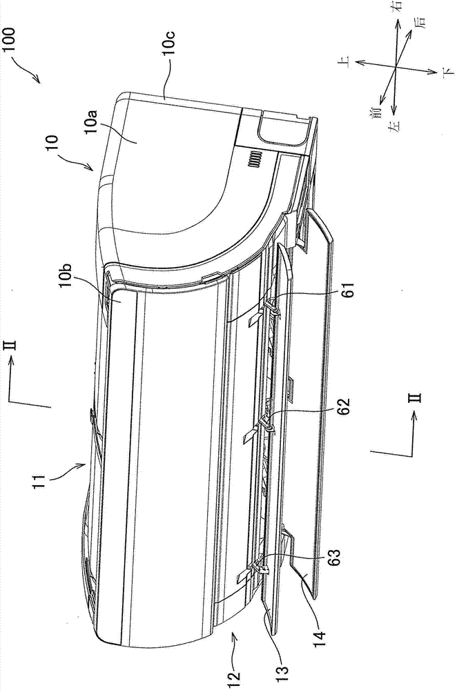
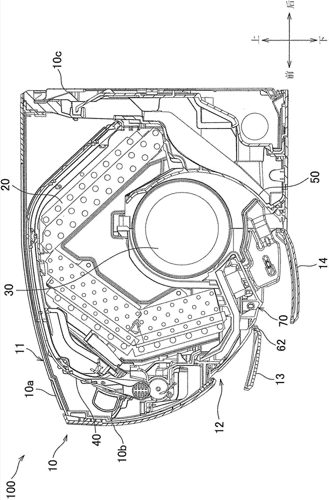
[0036] Below, refer to Figure 1 to Figure 8 Embodiments of the present invention will be described.

[0037] (The overall structure of the indoor unit of the air conditioner)

[0038] Air conditioner indoor unit 100 such as figure 1 , 2 Shown is a wall-mounted indoor unit including a substantially rectangular parallelepiped main body case 10 , a heat exchanger 20 disposed inside the main body case 10 , an indoor fan 30 , a filter 40 , and a chassis 50 .

[0039] (main body shell)

[0040] The main body housing 10 such as figure 1 , 2 It is shown with a front grill 10a, a front panel 10b covering the front surface of the front grill 10a, and a mounting plate 10c disposed at the rear end of the front grill 10a. The upper end of the front panel 10b is rotatably supported by the front grill 10a, and the front panel 10b can be operated as a hinge.

[0041] In addition, an intake port 11 is formed at the upper portion of the main body case 10 , and an exhaust port 12 is form...


PUM


Abstract

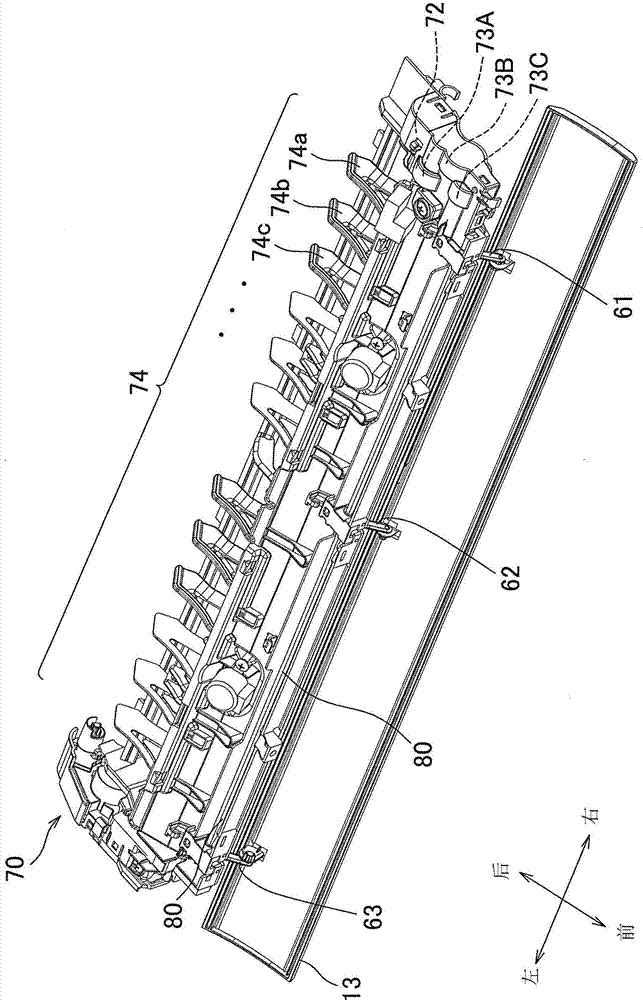
The invention discloses an air conditioner indoor unit capable of inhibiting a gap between a baffle plate and a housing under the closed state of the baffle plate. An exhaust opening of the air conditioner indoor unit is provided with a first baffle plate (13). The first baffle plate (13) is connected with a shaft (80) disposed on a rear side by arms (61,62,63). The right side of the shaft (80) is provided with a motor, and can rotate under the driving of the motor along with the first baffle plate (13). The arms (61,62,63) are respectively disposed on the right end part, the central part, and the left end part of the first baffle plate (13).The arms (61,62,63) are disposed on the shaft (80) in a staggered manner along the rotating direction of the closing motion of the first baffle plate (13).

Description

technical field [0001] The invention relates to an air conditioner indoor unit. Background technique [0002] As the air-conditioning indoor unit, an air-conditioning indoor unit including a casing, a heat exchanger and a fan housed in the casing is known. The air sucked into the casing passes through the heat exchanger, and is blown out from the exhaust port formed in the lower part of the casing. Here, a baffle is arranged along the longitudinal direction at the exhaust port, and the wind direction of the air blown out from the exhaust port can be changed by rotating the baffle (Patent Document 1, etc.). [0003] In addition, in the casing, a shaft is disposed behind the baffle, and the baffle is connected to the shaft via an arm. Then, the shaft is rotated by driving a motor arranged at one end side in the longitudinal direction of the shaft, and the flapper rotates accordingly. [0004] [Prior Art Literature] [0005] 【Patent Literature】 [0006] [Patent Document 1]...

Claims


Application Information

Patent Timeline
Patent Type & Authority Applications(China)
IPC IPC(8): F24F13/14
Inventor 安富正直平木雅人
Owner DAIKIN IND LTD
Learn More