Strobe device

A strobe and trigger coil technology, applied to lighting devices, components of lighting devices, circuit layout, etc., can solve problems such as light reduction and light fluctuations

Inactive Publication Date: 2014-04-09
PANASONIC CORP
View PDF5 Cites 0 Cited by
  • Summary
  • Abstract
  • Description
  • Claims
  • Application Information

AI Technical Summary

Problems solved by technology

Therefore, there are problems such as a decrease in the light quantity of the light emitted from the flash discharge tube or fluctuations in the light quantity depending on the discharge position.

Method used


Image

  • Strobe device
  • Strobe device
  • Strobe device

Examples


Embodiment approach

[0024] Below, use Figure 1 to Figure 7B The strobe device according to the embodiment of the present invention will be described.

[0025] First, use Figure 1 to Figure 3 The outline of the strobe device according to the embodiment of the present invention will be described.

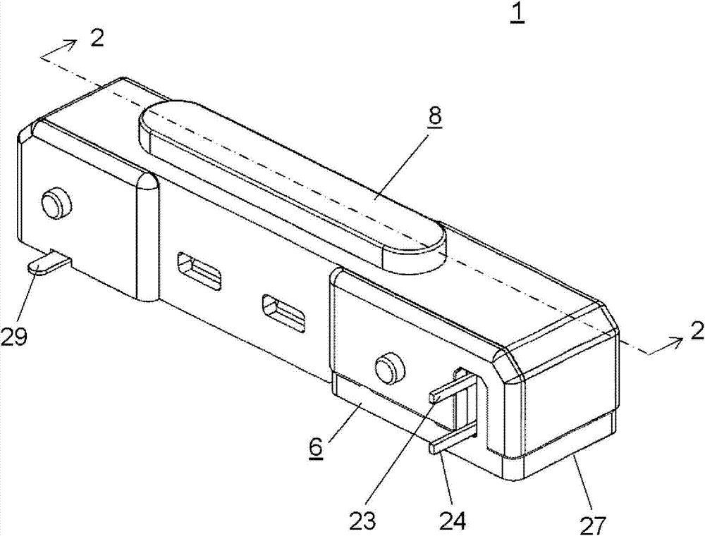
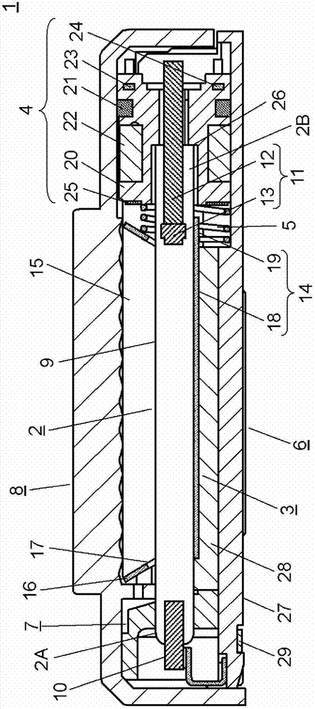
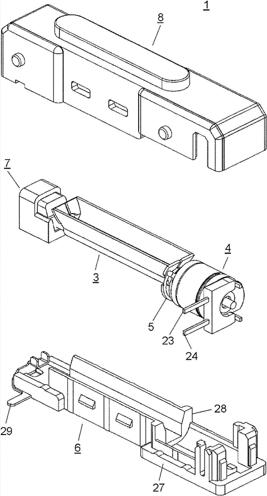
[0026] figure 1 It is a perspective view of a strobe device according to an embodiment of the present invention. figure 2 Is the strobe device involved in this embodiment figure 1 A cross-sectional view of line 2-2. image 3 It is an exploded perspective view of the strobe device according to this embodiment.

[0027] Such as figure 1 As shown, the strobe device 1 of this embodiment includes a base body 6 composed of a main body 27 having an anode terminal portion 29, an optical panel 8 fitted to the main body 27, and a primary terminal portion 23 of a trigger coil (not shown). The common terminal portion 24 and the anode terminal portion 29 are protrudingly provided as external terminals.

[0028] In additio...


PUM


Abstract

This strobe device is provided with: a flash discharge tube that has an anode disposed on one end side and a cathode disposed on the other end side and provided with a metal sintered body on a leading end part; an electrically conductive reflector that constitutes a trigger outside electrode that accommodates part of the flash discharge tube; and a trigger coil having a primary winding and a secondary winding wound around a hollow core. A part of the flash discharge tube cathode that does not include the metal sintered body is inserted into the trigger coil core, and the reflector is provided with a base part in contact with an outer peripheral surface of the flash discharge tube so as to cover at least the part between the anode and cathode and the metal sintered body and is also connected to the secondary winding of the trigger coil. Thus, a strobe device with little variation in intensity can be achieved.

Description

Technical field [0001] The present invention relates to, for example, a strobe device for photographing. Background technique [0002] At present, the following strobe device is known. The strobe device is provided with: a flash discharge tube having an anode arranged on one end side and a cathode arranged on the other end side and provided with a metal sintered body at the tip; a reflector, It houses a part of the flash discharge tube inside; the trigger coil has a primary winding and a secondary winding around the outer circumference of a cylindrical iron core. [0003] In the above stroboscopic device, a conductive thin-film transparent electrode is provided on the surface of the flash discharge tube, and the secondary winding of the trigger coil is connected to the thin-film transparent electrode of the flash discharge tube. As a result, the thin-film transparent electrode functions as a trigger external electrode to light up the flash tube. [0004] In addition, in the above-m...

Claims


Application Information

Patent Timeline
Patent Type & Authority Applications(China)
IPC IPC(8): G03B15/05F21V7/00F21V23/00G03B15/02G03B15/03
CPCG03B15/02G03B15/05F21V23/02F21V7/005G03B2215/0532G03B2215/0578G03B15/03
Inventor 近藤隆男高崎晃史牧寿纪村井利彰
Owner PANASONIC CORP
Why Eureka
Try Eureka