Contour microscopic method
A technology for profiling and detecting optical fibers, which is applied in the field of microscopic methods and devices for profiling, can solve the problems that cannot meet the super-resolution requirements of micro-scale structures, and achieve the effect of remarkable lateral resolution, simple structure, and improved lateral resolution
- Summary
- Abstract
- Description
- Claims
- Application Information
AI Technical Summary
Problems solved by technology
Method used
Image
Examples
Embodiment 1
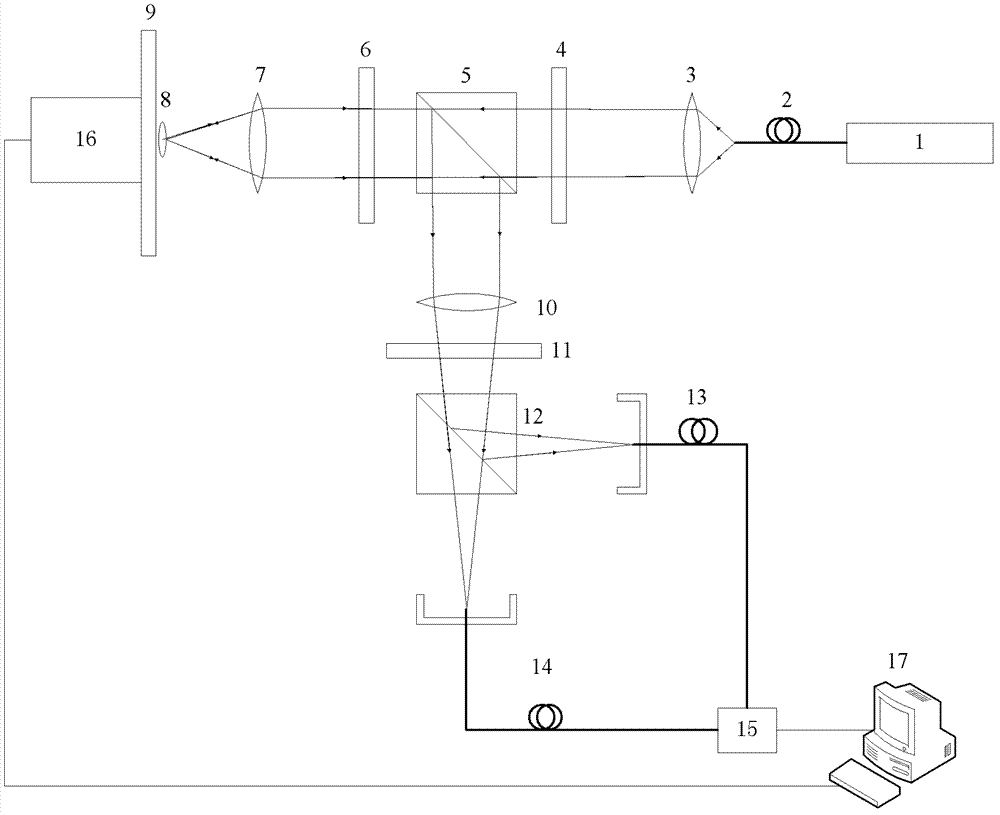
[0054] Such as figure 1 As shown, a microscopic device of a profile includes: a laser 1, a single-mode fiber 2, a first collimator lens 3, a first polarizer 4, a first polarizing beam splitter 5, a quarter wave plate 6, Second lens 7, sample platform 9, third lens 10, half-wave plate 11, second polarization beam splitter 12, second detection fiber 13, first detection fiber 14, differential detector 15, nano-translation stage 16, main control computer 17.
[0055] Wherein, the laser 1 emits a laser beam, and the single-mode fiber 2, the first collimating lens 3, the first polarizer 4, the first polarizing beam splitter 5, the quarter-wave plate 6 and the second lens 7 are sequentially arranged on the laser beam. on the optical axis of the beam path. The exit end face of the single-mode optical fiber 2 is located at the object focus of the first collimating lens 3, the single-mode optical fiber 2 and the first collimating lens 3 collimate the laser beam, and the first polarize...
Embodiment 2
[0069] use figure 1 When the shown device carries out the microscopy of the profile, in step (4), the fiber end face of the first detection fiber 14 and the fiber end face of the second detection fiber 13 move vertically along the same direction on the plane where they are respectively (simultaneously upward move or move downward at the same time), correspondingly, in subsequent steps (5)-(7), the surface of the sample to be tested is scanned vertically.
Embodiment 3
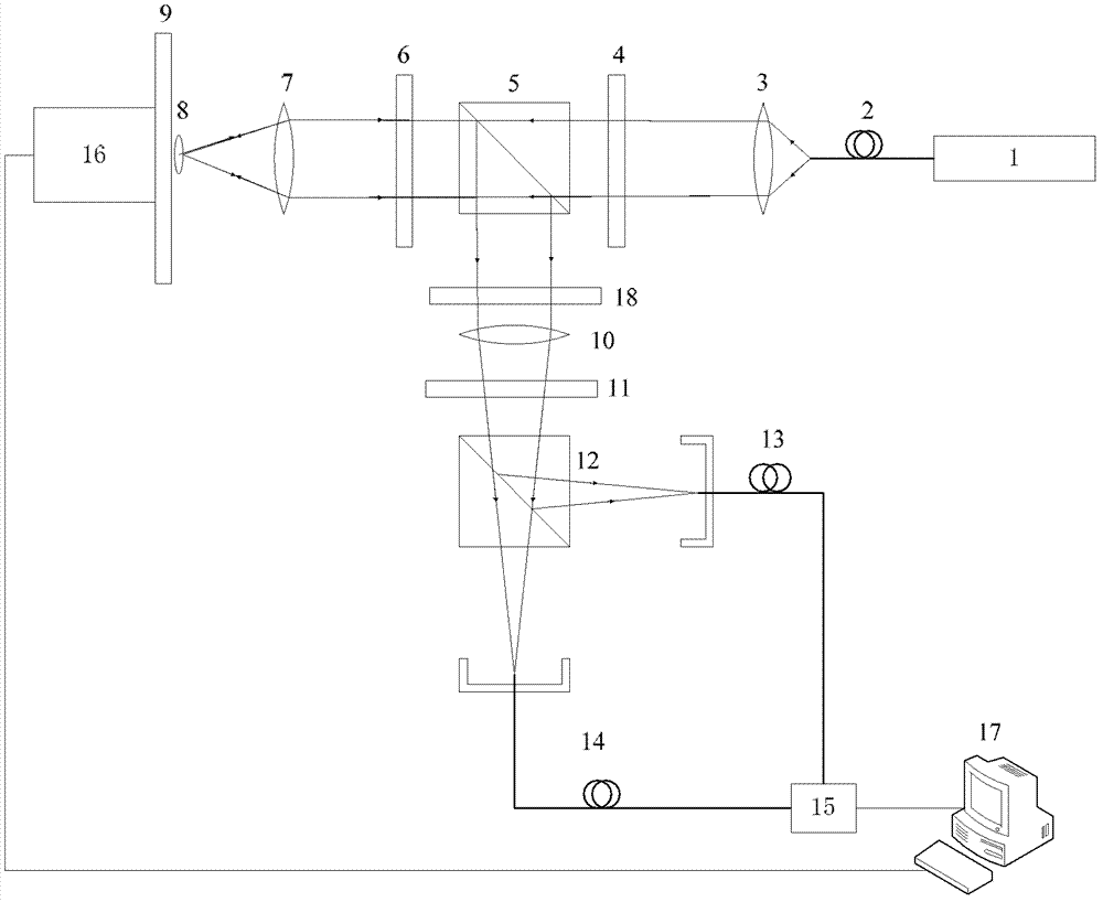
[0071] Such as figure 2 The micro-device shown in the profile is only different from Embodiment 1 in that the device also includes a 0 / π phase plate 18, wherein the 0 / π phase plate 18 is placed between the first polarizing beam splitter 5 and the third lens Between 10, the 0 / π phase division line of the 0 / π phase plate 18 passes through the center of the beam obtained by focusing the third lens 10 and is perpendicular to the center of the fiber end face of the first detection fiber 14 and the fiber end face of the second detection fiber 13 The connection formed by the center.
[0072] use figure 2 The microscopic method that the shown device realizes profile is also roughly the same as the method in Example 1, and its difference is only that step (4) is replaced as follows:
[0073] (4) First place a 0 / π phase plate 18 between the first polarizing beam splitter 5 and the third lens 10, and the 0 / π phase dividing line of the 0 / π phase plate 18 passes through the beam obtain...
PUM
 Abstract
Description
Claims
Application Information
 - R&D
- Intellectual Property
- Life Sciences
- Materials
- Tech Scout
- Unparalleled Data Quality
- Higher Quality Content
- 60% Fewer Hallucinations
Browse by: Latest US Patents, China's latest patents, Technical Efficacy Thesaurus, Application Domain, Technology Topic, Popular Technical Reports.
© 2025 PatSnap. All rights reserved.Legal|Privacy policy|Modern Slavery Act Transparency Statement|Sitemap|About US| Contact US: help@patsnap.com


