Vehicle driving setting device and setting method thereof

A vehicle drive and setting device technology, applied in the direction of control drive, control device, vehicle components, etc., can solve the problems of small rotation angle, short rotation time, slow rotation speed, etc., to avoid damage to components and improve applicability.

Active Publication Date: 2014-04-16
KYMCO
View PDF5 Cites 0 Cited by
  • Summary
  • Abstract
  • Description
  • Claims
  • Application Information

AI Technical Summary

Problems solved by technology

However, the motor 12 rotates under the control of the drive circuit 11, but if the rotation speed of the motor is unstable, it is easy to cause the stop position of the drive setting module 14 to be incorrect.
If the motor rotates too fast, the rotation time is too long, the rotation angle is too large or the number of rotations is too many, it is easier to make the support rod 17 get stuck between the switch plate and the main body of the micro swi

Method used


Image

  • Vehicle driving setting device and setting method thereof
  • Vehicle driving setting device and setting method thereof
  • Vehicle driving setting device and setting method thereof

Examples


Example Embodiment

[0044] The preferred embodiments of the present invention will be described in detail as follows by combining the drawings.

[0045] See Figure 2A A schematic diagram showing the first structure of a vehicle drive setting device according to an embodiment of the present invention, Figure 2B with Figure 2C The first hardware structure diagram of the vehicle drive setting device according to the embodiment of the present invention is shown.

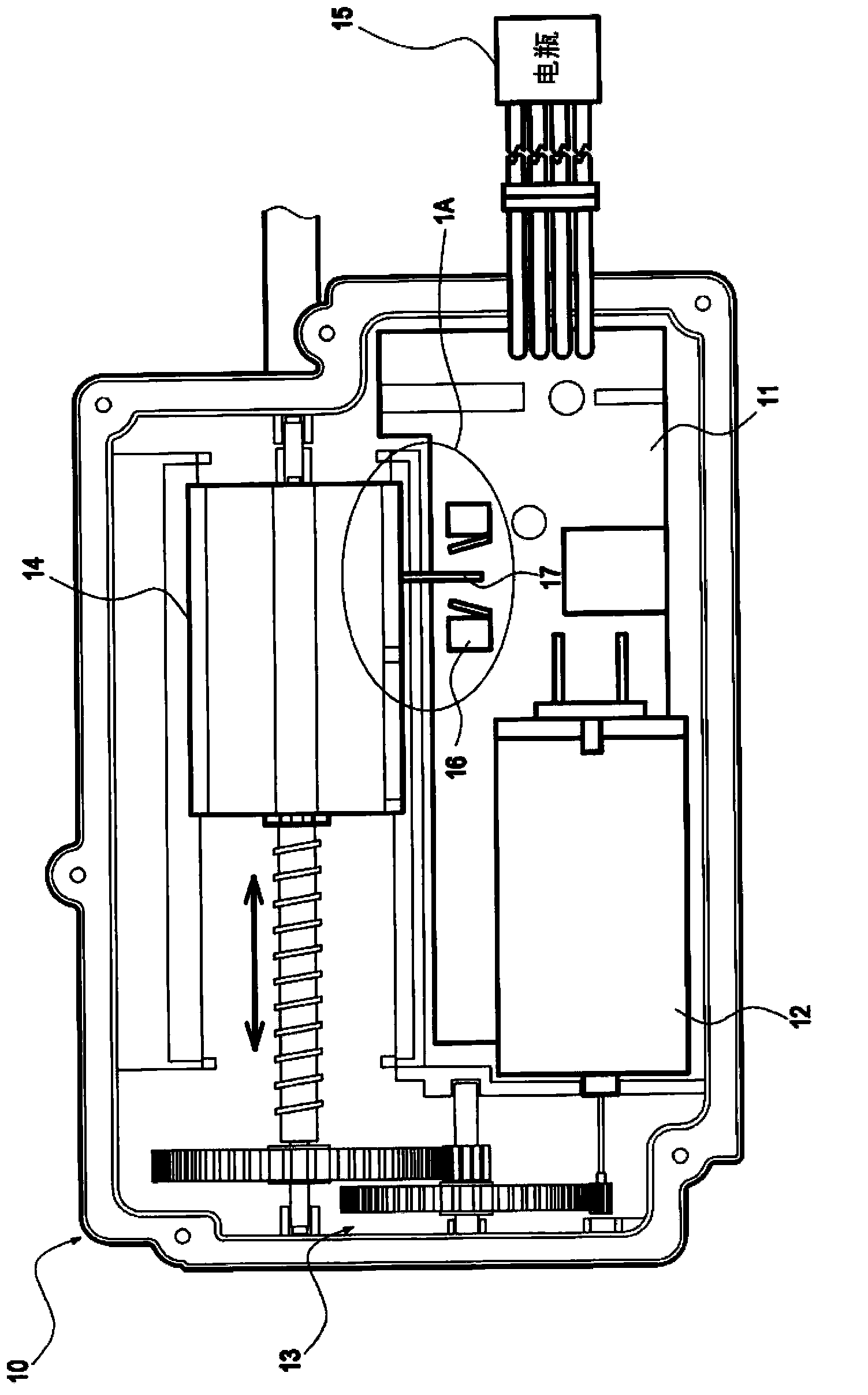
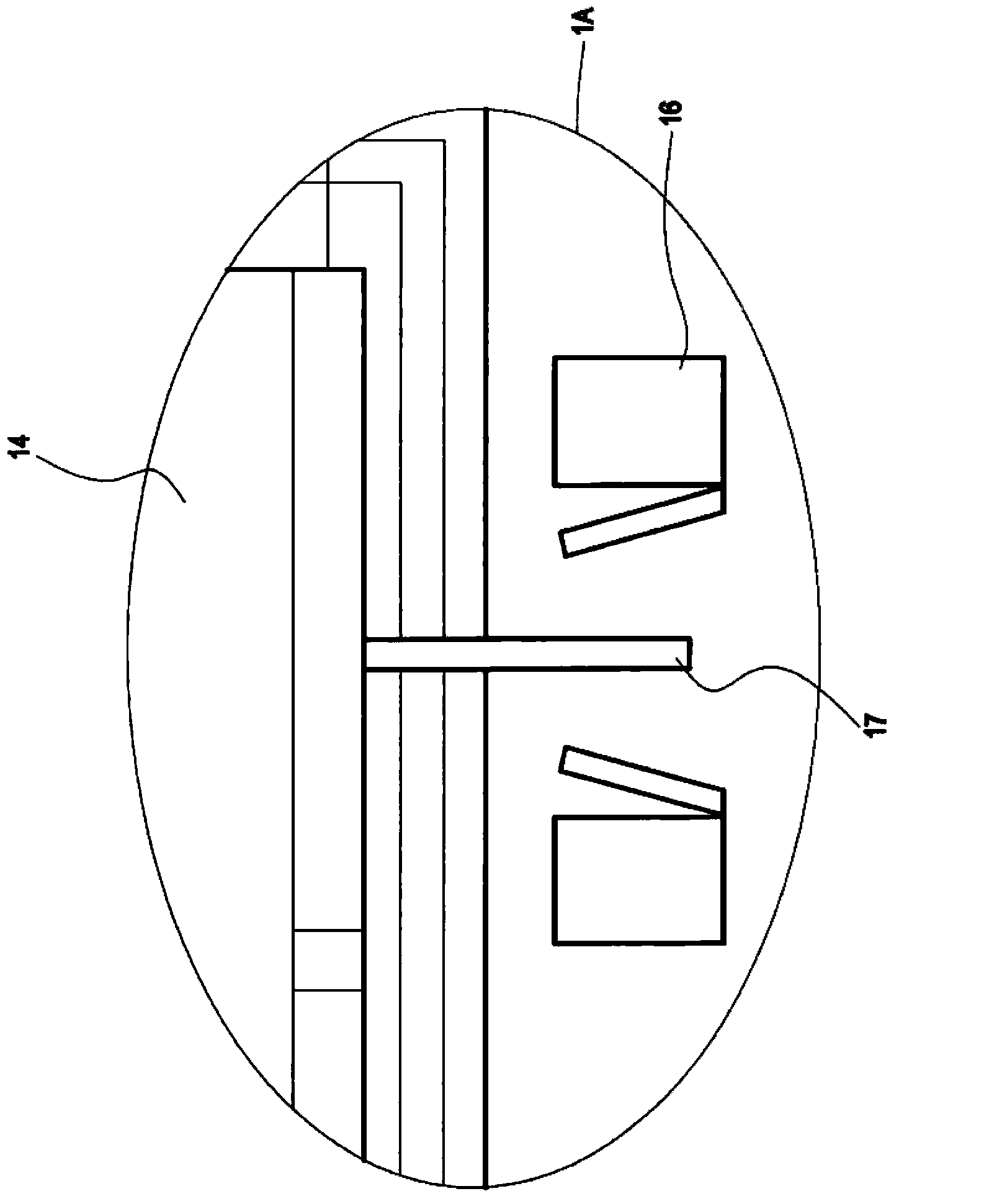
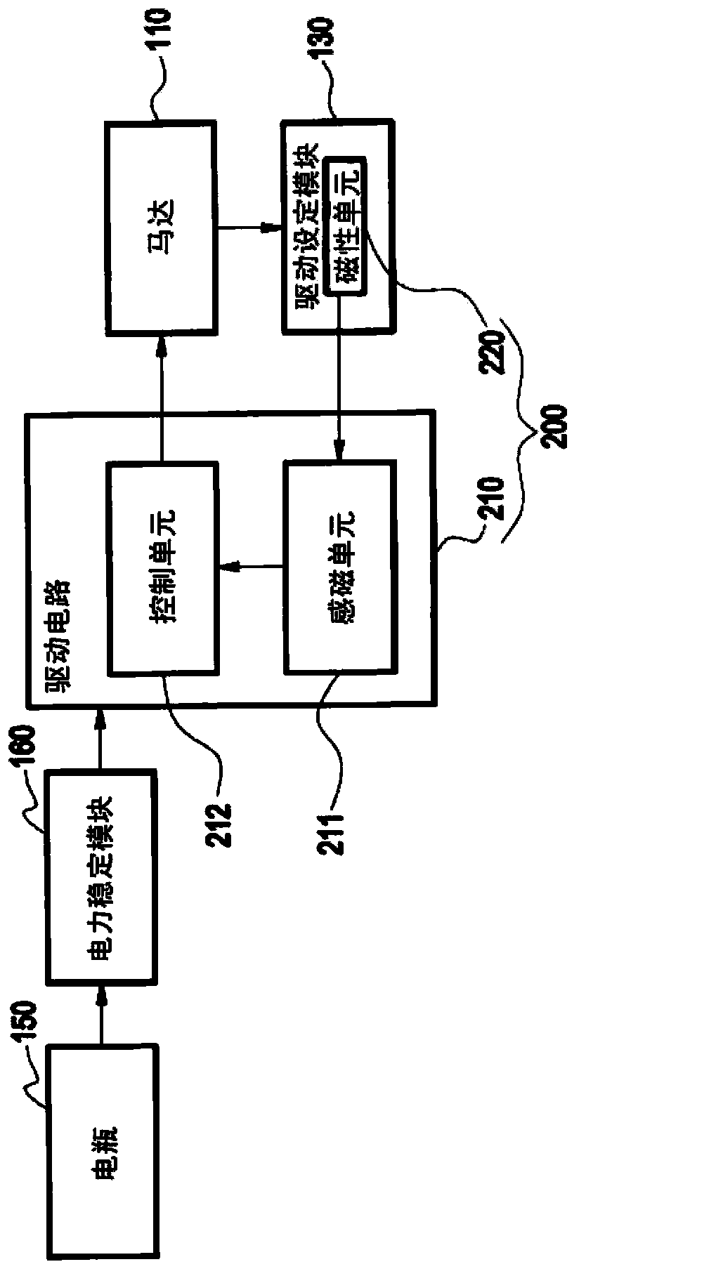
[0046] The vehicle drive setting device 200 is provided in the actuator 100. The actuator 100 further includes a motor 110, a gear set 120 and a drive setting module 130. Here, the gear set 120 uses the first gear 121 and the second gear 122 toothed with each other as an example, but it is not limited to this, and other similar gear sets 120 are also applicable, depending on the needs of the designer.

[0047] The motor 110 is toothed to the first gear 121, the second gear 122 has a pivot 123 with a spiral pattern on the pivot 123, and a corre...


PUM


Abstract

The invention discloses a vehicle driving setting device and a setting method thereof. The vehicle driving setting device and the setting method thereof are suitable for an actuator of a vehicle. The actuator comprises a motor, a gear set and a driving setting module. Through synergy driving of the gear set, rotation of the motor enables the driving setting module to make displacement, so that the driving mode of the vehicle is set. The vehicle driving setting device comprises a magnetic unit and a driving circuit. The magnetic unit is arranged on the driving setting module. The driving circuit is connected with the motor and comprises a plurality of magnetic sensing units and a control unit. The control unit is used for driving the motor to rotate and stop, and adjusting driving setting of the motor according to the sensing result of the magnetic sensing units to the magnetic unit.

Description

Technical field [0001] The present invention relates to a vehicle drive setting device and a drive setting method, and more particularly to a drive setting device and a drive setting method from an electric vehicle to an electric vehicle or a battery pack to a vehicle. Background technique [0002] See Figure 1A with Figure 1B A schematic diagram showing the structure of a prior art vehicle actuator. The actuator 10 includes a drive circuit 11, a motor 12, a gear set 13 and a drive setting module 14. The driving circuit 11 is connected to the battery 15 for receiving power and for controlling the rotation of the motor 12. The rotation of the motor 12 will drive the gear set 13 to operate, and the drive setting module 14 connected to the gear set 13 will be driven by the gear set 13 to generate displacement. Therefore, the rotation time, rotation angle and number of rotations of the motor 12 will affect the displacement distance and the stop position of the driving setting modu...

Claims


Application Information

Patent Timeline
IPC IPC(8): B60K17/12B60L15/20
CPCY02T10/72
Inventor 谢世甲郭永吉吕坤郎
Owner KYMCO
Why Eureka
Try Eureka