Slide-moving mechanism

A technology of sliding mechanism and reducer, which is applied in conveyors, mechanical conveyors, transportation and packaging, etc. It can solve the problems of not being able to meet the demand, unable to set up sliding platforms at the same time, limiting the efficiency of the sliding mechanism, etc., to achieve the processing procedure smooth and efficient effect

Active Publication Date: 2014-04-16
四川成焊宝玛焊接装备工程有限公司
View PDF11 Cites 4 Cited by
  • Summary
  • Abstract
  • Description
  • Claims
  • Application Information

AI Technical Summary

Problems solved by technology

However, when using the cylinder push method, it is impossible to set up a plurality of independent sliding platforms on a sliding mechanism at the same time, so that after each processing is completed, the components to be processed must be reinstalled on the sliding platform and moved to the processing position, greatly Limiting the efficiency of the sliding mechanism, it has been increasingly unable to meet the needs of actual production

Method used


Image

  • Slide-moving mechanism
  • Slide-moving mechanism
  • Slide-moving mechanism

Examples


Embodiment Construction

[0018] The present invention will be further described below in conjunction with the drawings and embodiments.

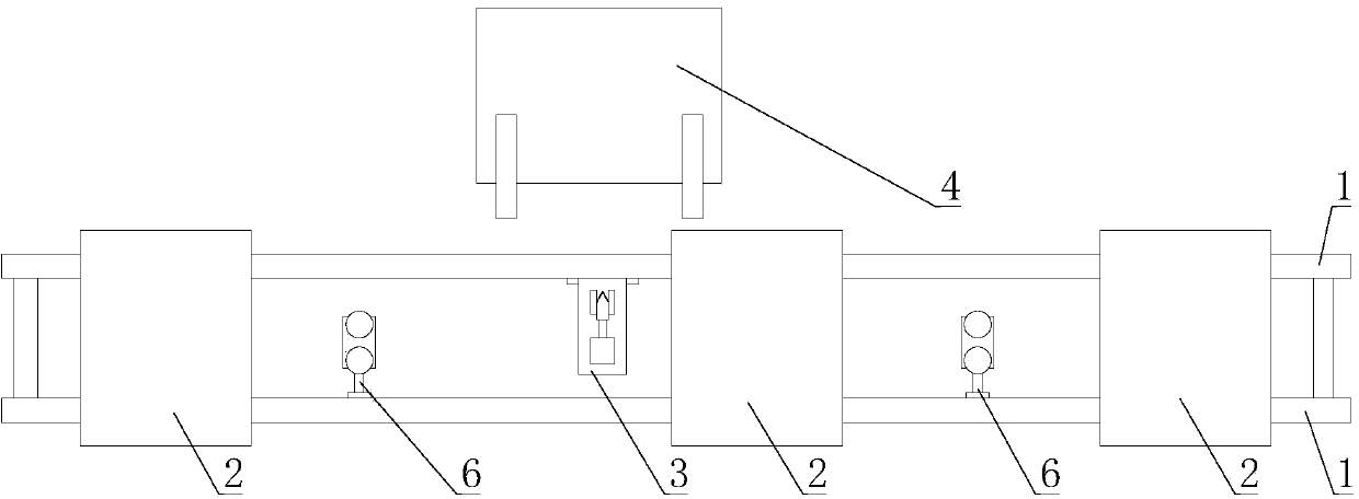
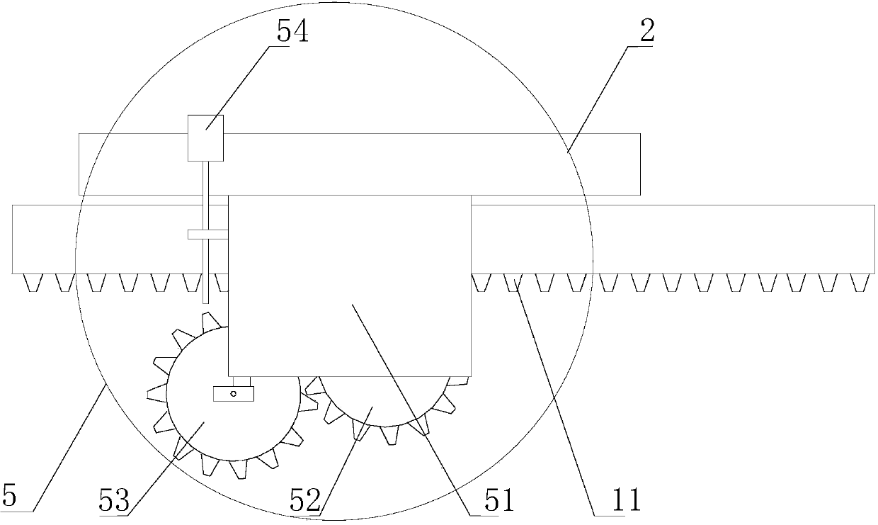
[0019] Such as Figure 1 to Figure 3 As shown, the sliding mechanism of the present invention includes two parallel guide rails 1 and a sliding platform 2 slidably connected to the guide rail 1. The guide rail 1 is provided with a rack 11 and a positioning device 3, and the positioning device 3 is facing the processing table. 4. A driving device 5 is provided on the sliding platform 2;

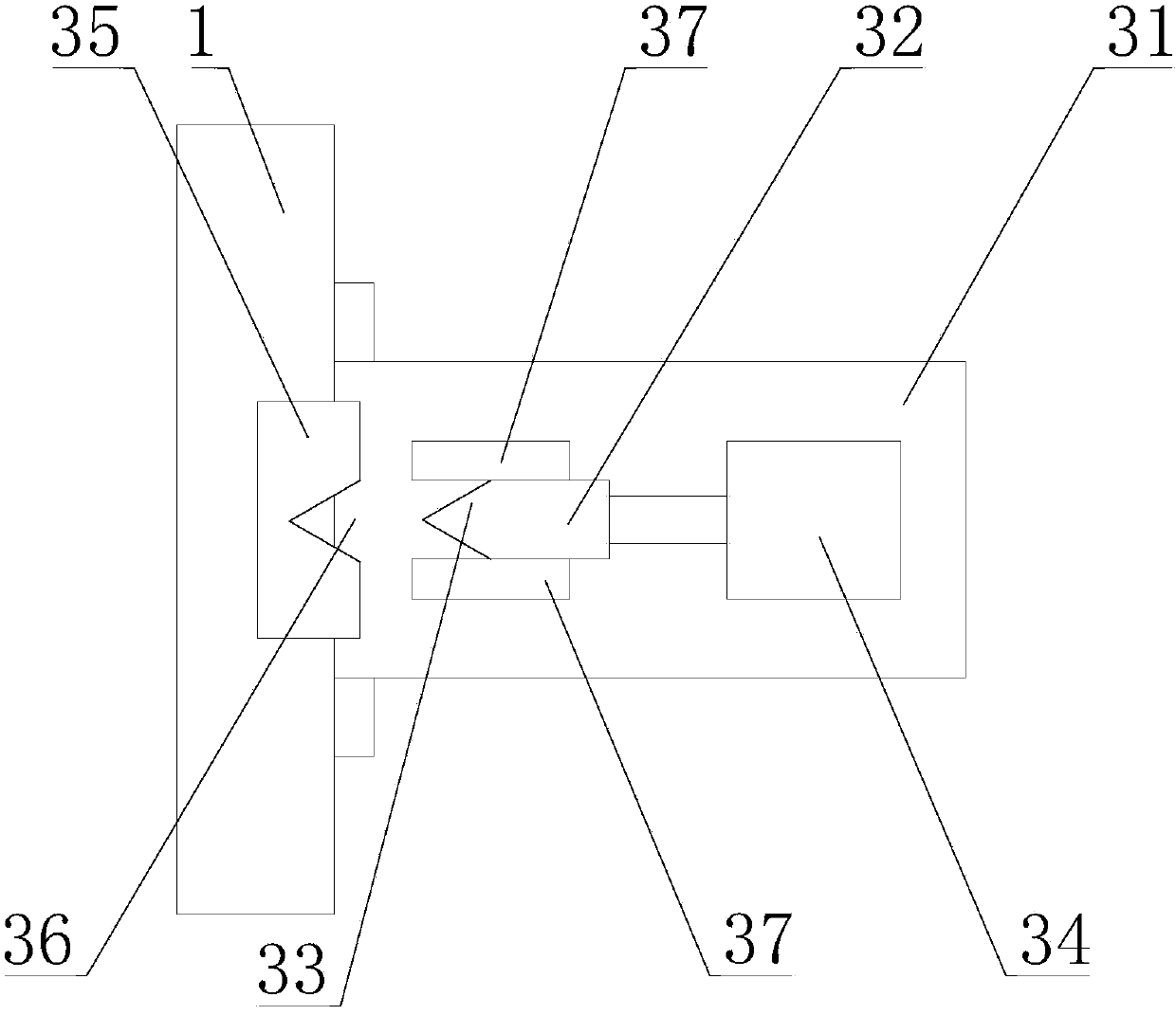
[0020] The positioning device 3 includes a base 31, the base 31 is fixed on the guide rail 1, a push block 32 is provided on the base 31, the front end of the push block 32 is provided with a protrusion 33, and the rear end of the push block is connected with an air cylinder 34, A positioning block 35 is provided at the bottom of the sliding platform 2, and a positioning groove 36 is provided on the positioning block 35, and the shape of the positioning groove 36 is consistent with the ...


PUM


Abstract

The invention discloses a slide-moving mechanism which is mainly used for moving components in the machining process. The slide-moving mechanism has the advantages of being simple in structure, high in efficiency and accurate in positioning. The slide-moving mechanism comprises two parallel guide rails and a sliding platform connected with the guide rails in a sliding mode. A rack and a positioning device are arranged on the guide rails, the positioning device is right opposite to a machining table, and driving devices are arranged on the two sides of the sliding platform. When the slide-moving mechanism works, the sliding platform is pushed by the driving devices 5, so that the sliding platform for carrying the components to be machined is made to move towards the machining table and then is accurately positioned through the positioning device. The slide-moving mechanism overcomes the defect that in the prior art, multiple sliding platforms cannot be erected on one slide-moving mechanism, the steps of mounting and detaching the components in the continuous machining process are eliminated, and thus the whole component machining process is more smooth and efficient.

Description

Technical field [0001] The invention relates to a mechanical carrying device, in particular to a sliding mechanism. Background technique [0002] In all kinds of mechanical processing and production, it is necessary to often use a sliding mechanism to move the component to the processing position for processing. At present, the sliding platform of the carrying member is generally moved to the processing position through the guide rail of the sliding mechanism by the way of pushing by the cylinder. However, when using the air cylinder to push, multiple independent sliding platforms cannot be erected on a sliding mechanism at the same time, so that the components to be processed must be reinstalled on the sliding platform and moved to the processing position after each processing is completed. Limiting the efficiency of the sliding mechanism, it has become increasingly unable to meet the needs in actual production. Summary of the invention [0003] The technical problem to be solv...

Claims


Application Information

Patent Timeline
Patent Type & Authority Applications(China)
IPC IPC(8): B65G35/00
Inventor 于成哉贺顺成刘照强
Owner 四川成焊宝玛焊接装备工程有限公司
Why Eureka
Try Eureka