Electronic equipment and antenna structure

A technology of electronic equipment and antenna structure, which is applied to antennas, loop antennas, antenna components, etc., can solve the problems of high installation cost, difficulty in wiring and wiring, and achieve the effect of reducing interference

Active Publication Date: 2022-01-18
HUAWEI TECH CO LTD
View PDF8 Cites 2 Cited by
  • Summary
  • Abstract
  • Description
  • Claims
  • Application Information

AI Technical Summary

Problems solved by technology

However, the PoE network cable needs to be installed through a window or through a wall, so it is difficult to manage and exit the cable
When the window gap of the user is small or there is no pre-set hole on the wall to borrow, professional engineering installation and drilling are required, and the installation cost is high

Method used


Image

  • Electronic equipment and antenna structure
  • Electronic equipment and antenna structure
  • Electronic equipment and antenna structure

Examples


Embodiment Construction

[0040] The technical solution in this application will be described below with reference to the accompanying drawings.

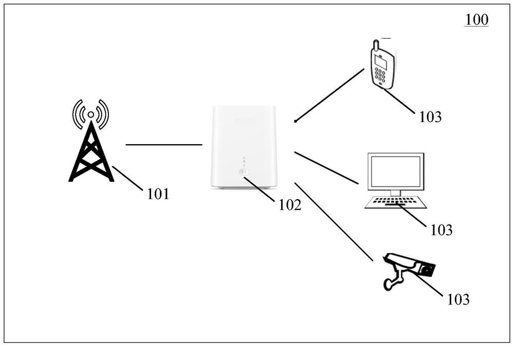
[0041] figure 1 is a schematic diagram of the architecture of the mobile communication system applicable to the embodiment of the present application.

[0042] Such as figure 1 As shown, the mobile communication system 100 may include at least one network device 101 , at least one CPE 102 and at least one user equipment (user equipment, UE) 103 . figure 1 It is only a schematic diagram, and the communication system may also include other network equipment, such as wireless relay equipment and wireless backhaul equipment, in figure 1 not shown in. The embodiments of the present application do not limit the number and specific types of network devices and UEs included in the mobile communication system.

[0043] The UE 103 in this embodiment of the present application may refer to a mobile phone, a tablet computer, a notebook computer, a smart bracelet, a sm...


PUM


Abstract

The invention provides electronic equipment. The electronic equipment comprises a low-frequency processing module, a high-frequency processing module, a coil and at least one capacitor, wherein the low-frequency processing module is electrically connected with two ends of the coil; the high-frequency processing module is electrically connected with the two ends of the coil; and each capacitor in the at least one capacitor is connected in parallel with the coil. The invention provides electronic equipment which can be applied to the field of wireless communication, cellular network signals sent by network equipment can be transmitted from outdoors to indoors in a wireless mode, a PoE network cable does not need to pass through a window or a wall, professional engineering installation and punching are omitted, and user experience can be greatly improved.

Description

technical field [0001] The present application relates to the field of wireless communication, in particular to an electronic device and an antenna structure. Background technique [0002] At present, a customer premise equipment (customer premise equipment, CPE) located outdoors transmits cellular network signals sent by a base station back indoors, usually using a power over ethernet (PoE) network cable. However, PoE network cables need to be installed through windows or walls, so it is difficult to manage and exit cables. When the window gap of the user is small or there is no pre-set hole on the wall to borrow, professional engineering installation and drilling are required, and the installation cost is high. This application provides a wireless data transmission solution to replace the traditional PoE network cable through the window or through the wall, avoiding the punching step because the cable needs to pass through the window and through the wall, and effectively ...

Claims


Application Information

Patent Timeline
Patent Type & Authority Applications(China)
IPC IPC(8): H04B1/40H01Q1/36H01Q23/00H02J50/10H02J50/20
CPCH04B1/40H01Q1/362H01Q23/00H02J50/10H02J50/20H01Q7/00H04B1/005H01Q25/005H01Q5/335H01Q5/50H04B1/0064
Inventor 王强王汉阳张琛聂成成李肖峰
Owner HUAWEI TECH CO LTD
Why Eureka
Try Eureka